Hyundai Elantra (CN7): Cylinder Head Assembly / Vacuum Pump
Repair procedures
| Removal |
| 1. | Disconnect the battery negative terminal. |
| 2. | Remove the air duct and air cleaner assembly. (Refer to Intake and Exhaust System - "Air Cleaner") |
| 3. | Remove the battery and battery tray. (Refer to Engine Electrical System - "Battery") |
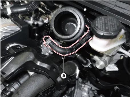
| 4. | Disconnect the brake vacuum hose (A).
|
| 5. | Disconnect the fuel hose (A) and PCSV hose (B).
|
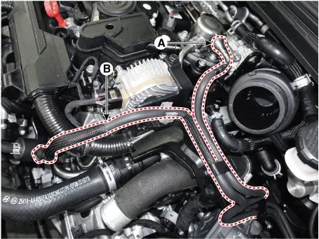
| 6. | Remove the main wiring protector (A) after disconnecting the connector (B).
|
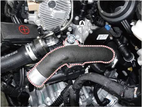
| 7. | Disconnect the intercooler inlet hose (A).
|
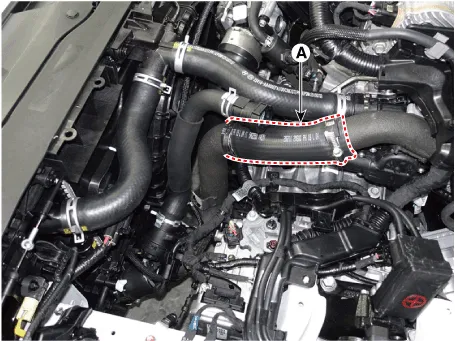

| 8. | Remove the intercooler pipe (A).
|
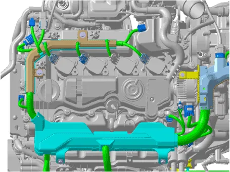
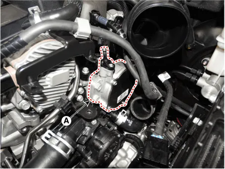
| 9. | Remove the vaccum pump (A).
|
| 10. | Install in the reverse order of removal. |
Repair procedures Removal • Use Fender cover to avoid damaging painted surfaces.• To avoid damaging the cylinder head, wait until the engine coolant temperature drops below normal temperature before removing it.
Other information:
Hyundai Elantra (CN7) 2021-2026 Service Manual: Front Radar Unit
Components and components location Components Location1. Front rader unit Specifications Specification Item Specification Power supply (V)12Operation voltage (V)9 - 16 Schematic diagrams Circuit DiagramTerminal function Pin No Te
Hyundai Elantra (CN7) 2021-2026 Service Manual: Warning Indicator
Components and components location Components1. BSD Indicator2. Side repeater lamp Repair procedures Inspection1.Disconnect the negative (-) battery terminal.2.Remove the front door trim.(Refer to Body - "Front door trim")3.Disconnect the power door mirror connector from the harness4.
Categories
- Manuals Home
- Hyundai Elantra Owners Manual
- Hyundai Elantra Service Manual
- Front Bumper
- Specifications
- Integrated Thermal Management Module (ITM)
- New on site
- Most important about car
