Hyundai Elantra (CN7): AVN System / Front monitor
Components and components location
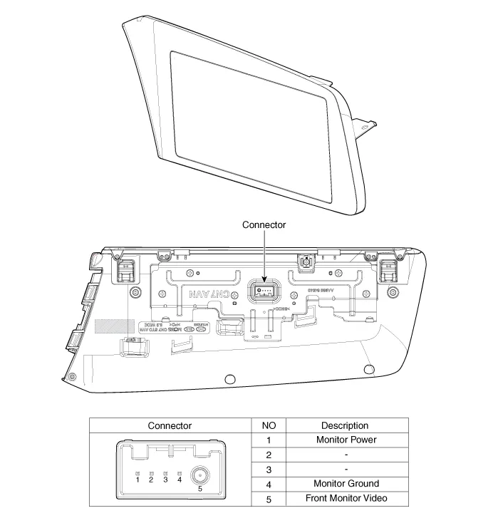
| Components |
Repair procedures
| Removal |
|

| 1. | Disconnect the negative (-) battery terminal. |
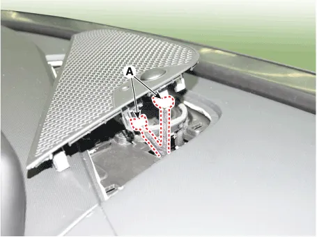
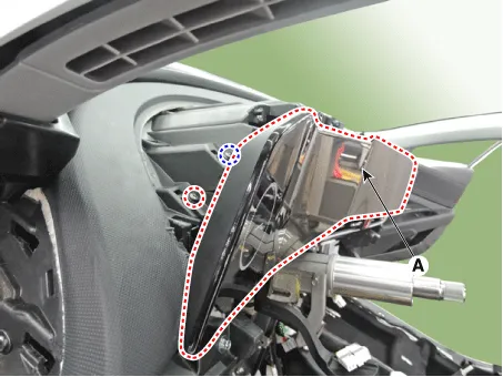
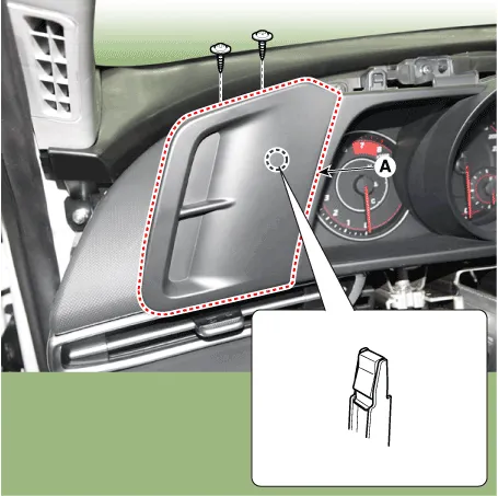
| 2. | Using a flat-tip screwdriver or remover, remove the photo sensor cover (A).
|

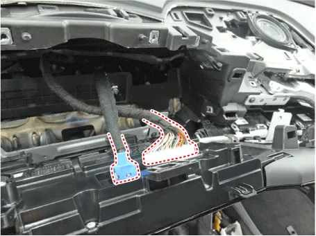
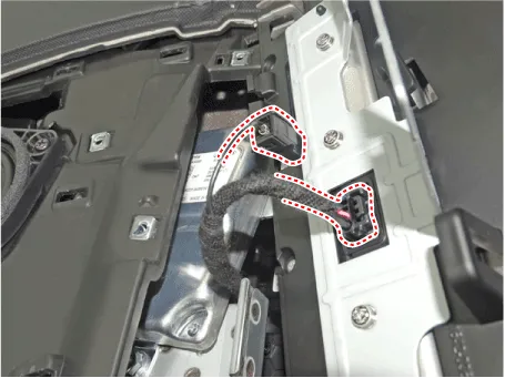
| 3. | Disconnect photo sensor connector and security sensor connector (A).
|
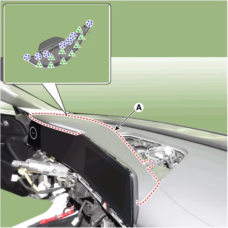
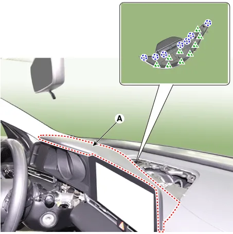
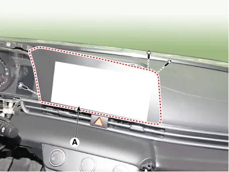
| 4. | Using a flat-tip screwdriver or remover, remove the cluster fascia upper garnish (A).
|
| 5. | Remove the AVN monitor (A) after loosening mounting screws.
|

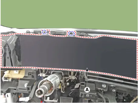
| 6. | Remove the AVN monitor after disconnecting cluster connectors and monitor connectors.
|
| 1. | Disconnect the negative (-) battery terminal. |
| 2. | Using a flat-tip screwdriver or remover, remove the photo sensor cover (A).
|
| 3. | Disconnect photo sensor connector and security sensor connector (A).
|
| 4. | Using a flat-tip screwdriver or remover, remove the cluster fascia upper garnish (A).
|
| 5. | Remove the cluster fascia side panel (A).
|
| 6. | Remove the cluster fascia panel (A) after loosening mounting screws.
|
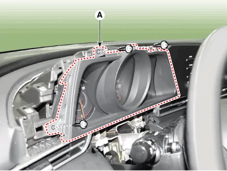
| 7. | Remove the AVN monitor (A) after loosening mounting screws.
|
| 8. | Remove the AVN monitor after disconnecting monitor connectors.
|
| Installation |
| 1. | Install the AVN monitor after connecting cluster connectors and monitor connectors. |
| 2. | Install the cluster fascia upper garnish. |
| 3. | Install photo sensor cover. |
| 4. | Connect the negative (-) battery terminal.
|
| 1. | Install the AVN monitor after connecting cluster connectors and monitor connectors. |
| 2. | Install the cluster fascia panel. |
| 3. | Install the cluster fascia side panel. |
| 4. | Install the cluster fascia upper garnish. |
| 5. | Install photo sensor cover. |
| 6. | Connect the negative (-) battery terminal.
|
Repair procedures Inspection1.Disconnector the negative (-) battery terminal.2.Remove the overhead console lamp.(Refer to Body Electrical System - "Overhead Console Lamp")3.
Other information:
Hyundai Elantra (CN7) 2021-2025 Service Manual: Head Lamp Leveling Switch
Schematic diagrams Schematic Diagrams Repair procedures Replacement1.Disconnect the negative (-) battery terminal.2.Remove the crash pad lower panel (A).(Refer to Body - "Crash Pad Lower Panel")3.Loosen the mounting screw and remove the crash pad lower switch (A).
Hyundai Elantra (CN7) 2021-2025 Service Manual: Description and operation
Description• PDW consists of 8 sensors (front : 4 units, rear : 4 units) that are used to detect obstacles and transmit the result in three separate warning levels, the first, second and third to IBU via LIN communication.• IBU decides the alarm level by the transmitted communication message from the slav
Categories
- Manuals Home
- Hyundai Elantra Owners Manual
- Hyundai Elantra Service Manual
- Engine Mechanical System
- Restraint
- Driver assistance system
- New on site
- Most important about car
