Hyundai Elantra (CN7): Fuel Delivery System / Fuel Pump Motor
Repair procedures
| Removal |
| 1. | Remove the fuel pump. (Refer to Fuel Delivery System - "Fuel Pump") |
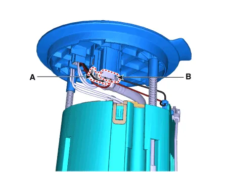
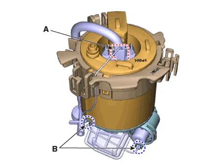
| 2. | Disconnect the fuel pump motor connector (A) and fuel sender connector (B).
|
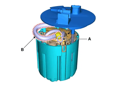
| 3. | Release the fixing hook (A) and then remove the fuel sender (B).
|

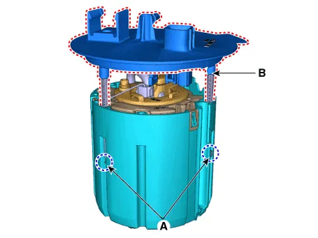
| 4. | Remove the fixing clip (A) and then disconnect the fuel feed tube (B).
|
| 5. | Remove the fixing clip (A) and then remove the head assembly (B).
|
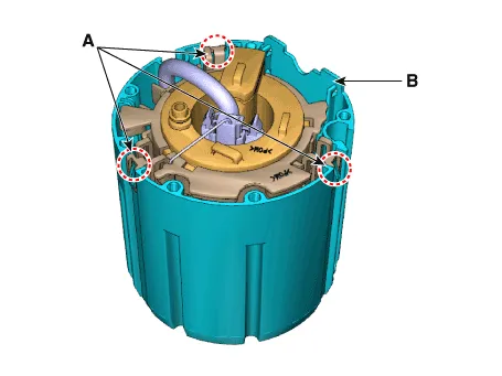
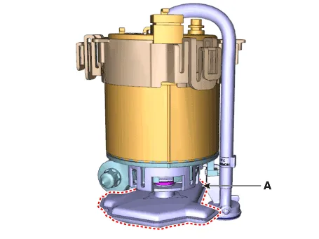
| 6. | Release the fixing hook (A) and then remove the reservoir-cup (B).
|
| 7. | Disconnect the fuel pump motor connector (A). |
| 8. | Disconnect the ground cable (B).
|
| 9. | Remove the fixing clip (A) and then disconnect the fuel pressure regulator (B).
|

| 10. | Release the fixing hook and then remove the free filter (A).
|
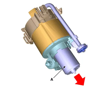
| 11. | Remove the fuel pump motor (A) from the fuel filter.
|

| Installation |
| 1. | Install in the reverse order of removal. |
Repair procedures Removal1.Remove the fuel pump. (Refer to Fuel Delivery System - "Fuel Pump")2.Disconnect the fuel pump motor connector (A) and fuel sender connector (B).
Repair procedures Removal1.Remove the fuel pump. (Refer to Fuel Delivery System - "Fuel Pump")2.Disconnect the fuel pump motor connector (A) and fuel sender connector (B).
Other information:
Hyundai Elantra (CN7) 2021-2026 Service Manual: Troubleshooting
TroubleshootingProblem Symptoms TableBefore replacing or repairing air conditioning components, first determine if the malfunction is due to the refrigerant charge, air flow or compressor.Use the table below to help you find the cause of the problem. The numbers indicate the priority of the likely cause of the problem.
Hyundai Elantra (CN7) 2021-2026 Service Manual: Refrigerant Line
Components and components location Components Location1. Refrigerant Pipe Assembly Repair procedures Replacement1.If the compressor is marginally operable, run the engine at idle speed, and let the air conditioning work for a few minutes, then shut the engine off.
Categories
- Manuals Home
- Hyundai Elantra Owners Manual
- Hyundai Elantra Service Manual
- Instrument Cluster
- Engine Mechanical System
- Rear Seats
- New on site
- Most important about car
