Hyundai Elantra (CN7): Heater / Heater Unit
Components and components location
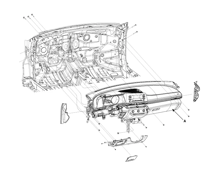
| Component Location |
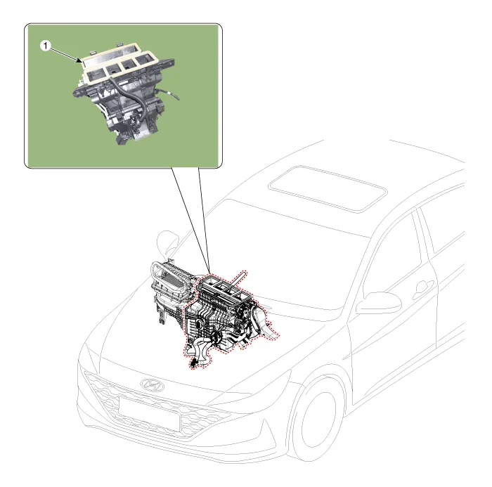
| 1. Heater unit assembly |
| Compoents |
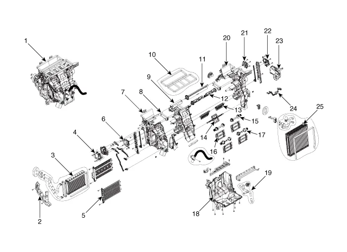
| 1. Heater unit assembly 2. Heater tube cover 3. Heater core assembly 4. Mode control actuator [LH] 5. Dummy PTC 6. Temperature control actuator [LH] 7. Heater case [LH] 8. Separator (Out) 9. Heater case [CTR] | 10. Heater & Blower duct seal 11. DEF door assembly 12. Vent door assembly 13. Floor door assembly 14. Mode door assembly 15. Shaft temperature door 16. Temperature door assembly 17. Shaft temperature door 18. Heater lower cover | 19. Drain hose 20. Heater case [RH] 21. Intake acutator 22. Temperature control actuator [RH] 23. Shower duct [RH] 24. Evaporator temperature sensor 25. Evaporator core assembly |
Repair procedures
| Replacement |
| 1. | Disconnect the negative (-) battery terminal. |
| 2. | Recover the refrigerant with a recovery / recycling / charging station. |
| 3. | When the engine is cool, drain the engine coolant from the radiator. (Refer to Engine Mechanical System - "Coolant") |
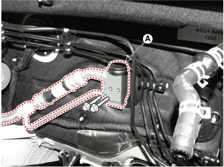
| 4. | Remove the bolts and the expansion valve (A) from the evaporator core.
|

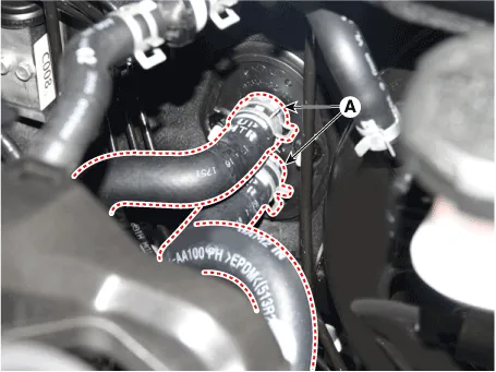
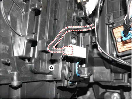
| 5. | Disconnect the heater hoses (A) from the heater unit.
|

| 6. | Remove the cowl top cover. (Refer to Body (Interior and Exterior) - "Cowl Top Cover") |
| 7. | Remove the battery. (Refer to Engine Electrical System - "Battery") |
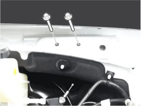
| 8. | Loosen the cowl cross member mounting bolts.
|
| 9. | Remove the front pillar trim. (Refer to Body (Interior and Exterior) - "Front Pillar Trim") |
| 10. | Remove the floor console assembly. (Refer to Body (Interior and Exterior) - "Floor Console Assembly") |
| 11. | Remove the shift lever assembly. (Refer to Automatic Transmission System - "Shift Lever") |
| 12. | Remove the cowl side trim. (Refer to Body (Interior and Exterior) - "Cowl Side Trim") |
| 13. | Remove the crash pad lower panel. (Refer to Body (Interior and Exterior) - "Crash Pad Lower Panel") |
| 14. | Remove the steering column shroud lower panel. (Refer to Body (Interior and Exterior) - "Steering Column Shroud Panel") |
| 15. | Remove the steering wheel. (Refer to Steering System - "Steering Wheel") |
| 16. | Remove the multifunction switch. (Refer to Body Electrical System - "Multifunction Switch") |
| 17. | Lower the steering column after loosening the mounting bolts. (Refer to Steering System - "Steering Column and Shaft") |
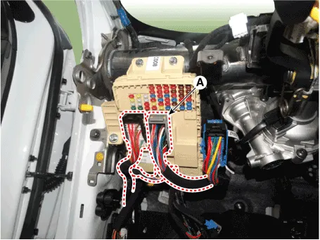
| 18. | Disconnect the junction box connectors (A).
|
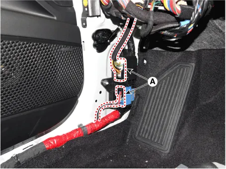
| 19. | Disconnect the multi box connectors (A). [LH]
[RH]
|
| 20. | Remove the center console duct (A).
|

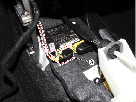
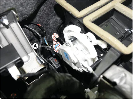
| 21. | Disconnect the airbag control module (SRSCM) connector (A).
|
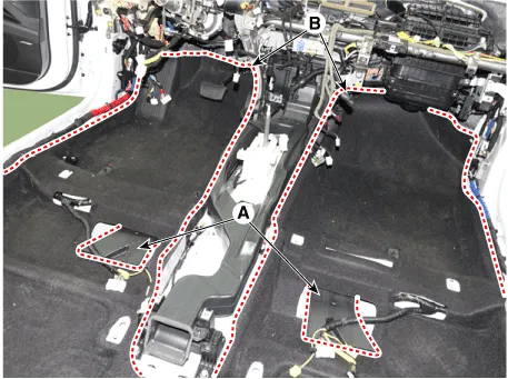
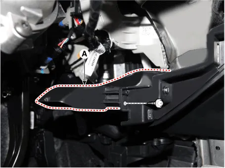
| 22. | Remove the rear air duct (A) and separate the floor carpet (B) to obtain space for removing the rear heating duct.
|
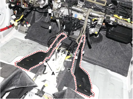
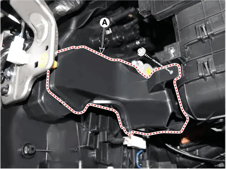
| 23. | Remove the front air duct (A).
|
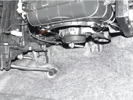
| 24. | Loosen the cowl blower unit mounting bolts.
|
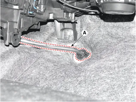
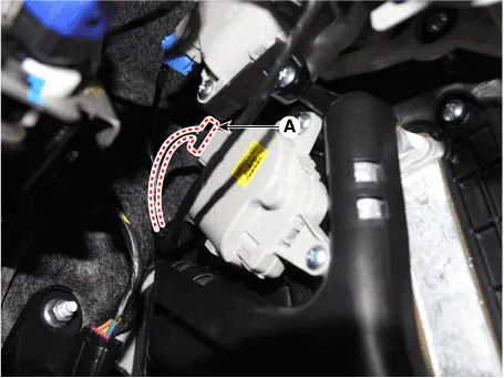
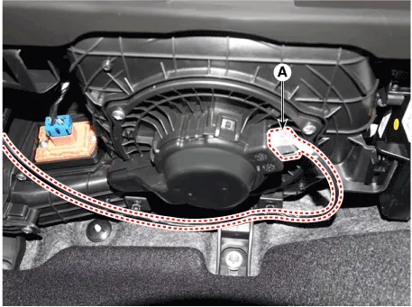
| 25. | Remove the drain hose (A).
|
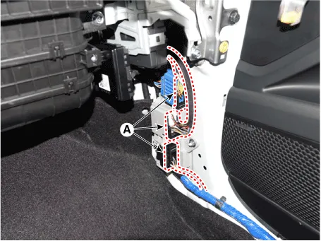
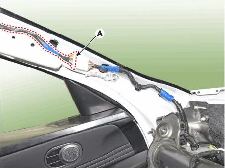
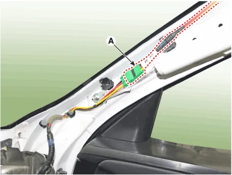
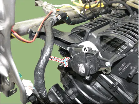
| 26. | Disconnect the connectors (A) and the mounting clips in the front pillar. [LH]
[RH]
|
| 27. | After loosening the bolts and nuts remove the main crash pad and cowl cross bar assembly (A) together.
|
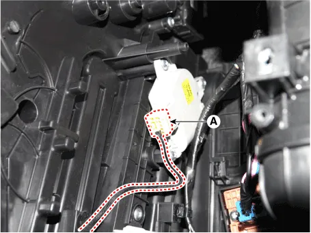
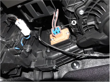
| 28. | Disconnect the heater & blower unit connectors. [Driver's side]
[Passenger's side]
|
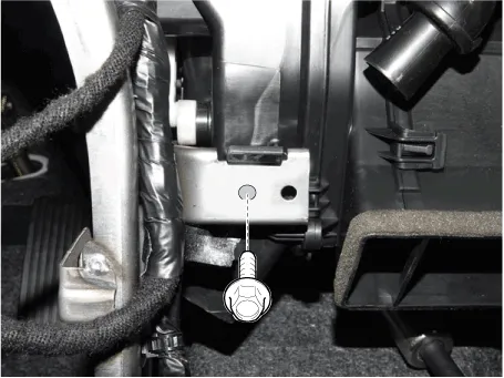
| 29. | Loosen the heater & blower unit mounting bolt.
|
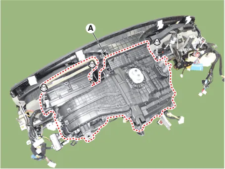
| 30. | Remove the heater and blower unit (A) from the crash pad after loosening the mounting nuts.
|
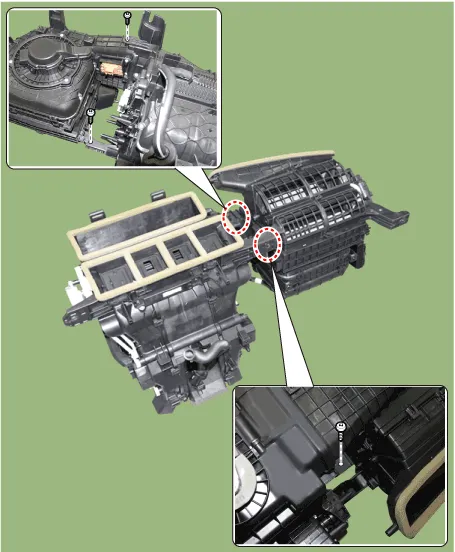
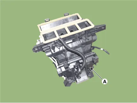
| 31. | Separate the heater unit (A) from the heater & blower unit assembly after loosening the screws.
|
| 32. | To install, reverse the removal procedure. |
Repair procedures Replacement1.Disconnect the negative (-) battery terminal. 2.Remove the heater and blower assembly.(Refer to Heater - "Heater Unit") 3.
Other information:
Hyundai Elantra (CN7) 2021-2026 Service Manual: Evaporator Core
Repair procedures Replacement1.Disconnect the negative (-) battery terminal. 2.Remove the heater and blower assembly.(Refer to Heater - "Heater Unit") 3.Remove the heater core cover (A) after loosening the mounting screws.4.Pull out the evaporator core (A) from the heater unit.
Hyundai Elantra (CN7) 2021-2026 Service Manual: Rear Corner Radar Unit
Specifications Specifications Items Blind-Spot Collision Warning (BCW) Blind-Spot Collision- Avoidance Assist-Rear (BCA-R) Rated voltageDC 12VOperating voltage9V - 16VOperating speed30 km/h - 255 km/h60 km/h - 180 km/hSensible distance70m Curvature radiusStart : More
Categories
- Manuals Home
- Hyundai Elantra Owners Manual
- Hyundai Elantra Service Manual
- Maintenance
- Suspension System
- Integrated Thermal Management Module (ITM)
- New on site
- Most important about car
