Hyundai Elantra (CN7): LCD Display / LCD Display Control
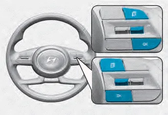
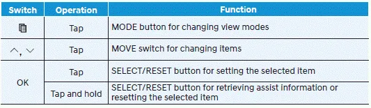
The LCD display modes can be changed by using the control buttons.
Information
When the infotainment system is applied, only the User’s Setting mode on the infotainment system is supported but the User’s Setting mode on the instrument cluster is not supported.
The information provided may differ depending on which functions are applicable to your vehicle.
Other information:
Hyundai Elantra (CN7) 2021-2026 Service Manual: Mood Lamp
Repair procedures RemovalMood lamp unit1.Disconnect the negative (-) battery terminal.2.Remove the main crash pad assembly.(Refer to Body - "Main Crash Pad Assembly")3.Loosen the mounting screws and remove the main crash pad air duct (A).4.Loosen the mounting screws and remove the mood lamp unit (A).
Hyundai Elantra (CN7) 2021-2026 Service Manual: Receiver-Drier
Repair procedures Replacement1.Remove the condenser.2.Remove the cap (A) on the bottom of the condenser with a L wrench. Tightening torque : 9.81 - 14.71 N.m (1.0 - 1.5 kgf.m, 7.2 - 10.8 lb-ft) 3.Remove the receiver-drier (A) from condenser using a long nose plier.
Categories
- Manuals Home
- Hyundai Elantra Owners Manual
- Hyundai Elantra Service Manual
- Front Radar Unit
- Vehicle Information
- Function settings
- New on site
- Most important about car
