Hyundai Elantra: Brake System / Master Cylinder
Components and components location
| Components |
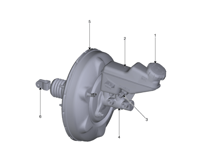
| 1. Reservoir cap 2. Reservoir 3. Brake fluid lever sensor | 4. Master cylinder 5. Brake booster 6. Push road |
Repair procedures
| Removal |
[LHD]
| 1. | Turn ignition switch OFF and disconnect the negative (-) battery cable. |
| 2. | Remove the brake fluid from the master cylinder reservior with a syringe.
|
| 3. | Remove the battery. (Refer to Engine Electrical System - "Battery") |
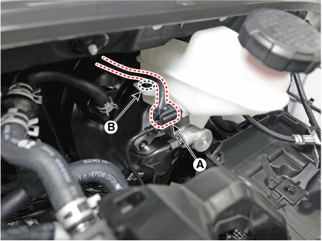
| 4. | Disconnect the brake fluid level sensor connector (A) and then removing the wiring clip (B).
|
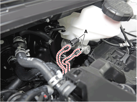
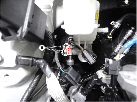
| 5. | Separate the brake tube (A) from the master cylinder by loosening the tube flare nut.
|
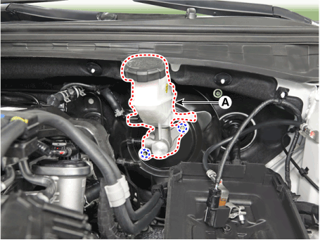
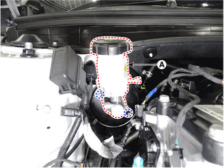
| 6. | Remove the master cylinder (A) after loosening the master cylinder nuts.
|
[RHD]
| 1. | Turn ignition switch OFF and disconnect the negative (-) battery cable. |
| 2. | Remove the brake fluid from the master cylinder reservior with a syringe.
|
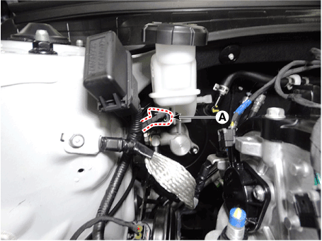
| 3. | Disconnect the brake fluid level sensor connector (A).
|
| 4. | Remove the brake tube after loosening the mounting bolts (A).
|
| 5. | Remove the master cylinder (A) after loosening the mounting nuts.
|
| Installation |
| 1. | To install, reverse the removal procedure.
|
| 2. | After installation, bleed the brake system. (Refer to Brake System - "Brake Bleeding Prcoedures") |
| 3. | Check the brake oil leakage and pedal operating condition. |
 Brake Booster
Components and components location
Components1. Reservoir cap2. Reservoir3. Brake fluid lever sensor4. Master cylinder5. Brake booster6. Push road
Repair procedures
Brake Booster Operating Test1...
 Brake Line
Components and components location
Components
Repair procedures
RemovalBrake Tube [Engine Room]1.Disconnect the brake fiuid level switch connector, and remove the reservoir cap...
Other information:
Hyundai Elantra (CN7) 2021-2025 Service Manual: Description and operation
DescriptionEmissions Control System consists of three major systems.• Crankcase Emission Control System prevents blow-by gas from releasing into the atmosphere. This system recycles gas back into the intake manifold (Closed Crankcase Ventilation Type)...
Hyundai Elantra (CN7) 2021-2025 Owner's Manual: Using ABS
To obtain the maximum benefit from your ABS in an emergency situation, do not attempt to modulate your brake pressure and do not try to pump your brakes. Depress your brake pedal as hard as possible. When you apply your brakes under conditions which may lock the wheels, you may hear sounds from the brakes, or feel a corresponding sensation in the brake pedal...
Copyright © 2025 www.helantra7.com


