Hyundai Elantra (CN7): Motor Driven Power Steering / MDPS PowerPack Assembly
Repair procedures
| Replacement |
| 1. | Turn the steering wheel so that the front wheels are placed in the straight ahead position.
|

| 2. | Turn the ignition switch OFF and disconnect the battery negative (-) cable.
|

| 3. | Remove driver airbag (DAB) module. (Refer to Restraint - "Driver Airbag (DAB) Module and Clock Spring") |
| 4. | Remove the steering wheel. (Refer to Steering System - "Steering Wheel") |
| 5. | Remove the clock spring. (Refer to Restraint - "Driver Airbag (DAB) Module and Clock Spring") |
| 6. | Remove the steering column shroud panel. (Refer to Body - "Steering Column Shroud Panel") |
| 7. | Remove the crash pad lower panel. (Refer to Body - "Crash Pad") |
| 8. | Remove the brake booster. (Only RHD) (Refer to Brake System - "Brake Booster") |
| 9. | Remove the brake pedal. (Only RHD) (Refer to Brake System - "Brake Pedal") |
| 10. | Disconnect the MDPS connector (A).
|
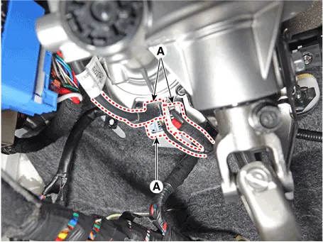
| 11. | Remove the wiring clip (A) from the steering column.
|
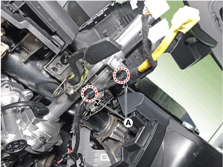
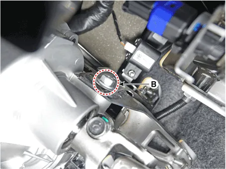
| 12. | Remove the steering column assembly after loosening the mounting nuts (A) and bolt (B).
|

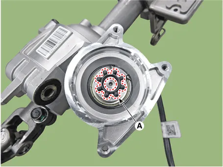
| 13. | Remove the MDPS power pack (A) after loosening the bolts.
|

| 14. | Install the new MDPS powerpack.
|

| 15. | To reassembly, reverse the disassembly procedure. |
| 16. | Conduct the "EPS Type Recognition" by diagnostic tool. (Refer to MDPS PowerPack Assembly - "Diagnosis with Diagnostic tool") |
| 17. | Conduct the "ASP Calibration" by diagnostic tool. (Refer to MDPS PowerPack Assembly - "Diagnosis with Diagnostic tool") |
| 18. | Erase DTC. |
| Diagnosis with Diagnostic tool |
| EPS Type Recognition |
|
| 1. | Connect self-diagnosis connector(16pins) located in the lower of driver side crash pad to self-diagnosis device. |
| 2. | Turn the self-diagnosis device after key is ON. |
| 3. | Turn the steering wheel to straight ahead position. |
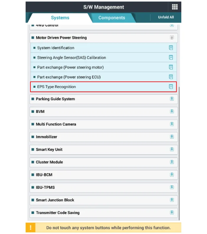
| 4. | After Selecting the "vehicle model" and "system", select the "EPS Type Recognition" on diagnostic tool vehicle selection screen.
|

| 5. | Remove the DTC. |
| 6. | Turn off the IG switch and wait for 20 seconds or more before starting the engine. And then make sure that MDPS works properly. SAS Calibration
|
| 1. | Connect self - diagnosis connector (16pins) located in the lower of driver side crash pad to self - diagnosis device. |
| 2. | Turn the self - diagnosis device after key is ON. |
| 3. | Turn the steering wheel to straight ahead position. |
| 4. | After Selecting the "vehicle model" and "system", select the "SAS Calibration" on diagnostic tool vehicle selection screen.
|


| 5. | Remove the DTC. |
| 6. | Turn off the IG switch and wait for 10 seconds or more before starting the engine. And then make sure that MDPS works properly. |
A/S Repair produresMDPS System A/S Workflow ※ For detailed DTC or other DTC A/S procedures, see "CN7 MDPS DTC Diagnostic Guide" ①Noise / malfunction Inspection② Warning lamp (DTC) / CAN Line error2 - 1 Checking Connectors and Wiring1.
Repair procedures Replacement1.Turn the steering wheel so that the front wheels are placed in the straight ahead position. • If the steering wheel and the front tires are not set straight ahead together, it may affect the number of circulation of steering wheel and damage the cable inside the clock spring.
Other information:
Hyundai Elantra (CN7) 2021-2026 Service Manual: General safety information and caution
Instructions (R-134a)When Handling Refrigerant1.R-134a liquid refrigerant is highly volatile. A drop on the skin of your hand could result in localized frostbite. When handling the refrigerant, be sure to wear gloves. 2.It is standard practice to wear goggles or glasses to protect your eyes, and gloves to protect your hands.
Hyundai Elantra (CN7) 2021-2026 Service Manual: Blower Unit
Components and components location Component Location1. Blower unit assemblyComponents1. Blower unit assebmly2. Blower upper cover [LH]3. Duct seal4. Blower upper cover [RH]5. Intake actuator6. Air filter cover7. Intake door8. Air filter9. Blower upper case10.
Categories
- Manuals Home
- Hyundai Elantra Owners Manual
- Hyundai Elantra Service Manual
- Components and components location
- Front Radar Unit
- Front Bumper
- New on site
- Most important about car
