Hyundai Elantra (CN7): Heater / Mode Control Actuator
Description and operation
| Description |
Components and components location
| Components Location |
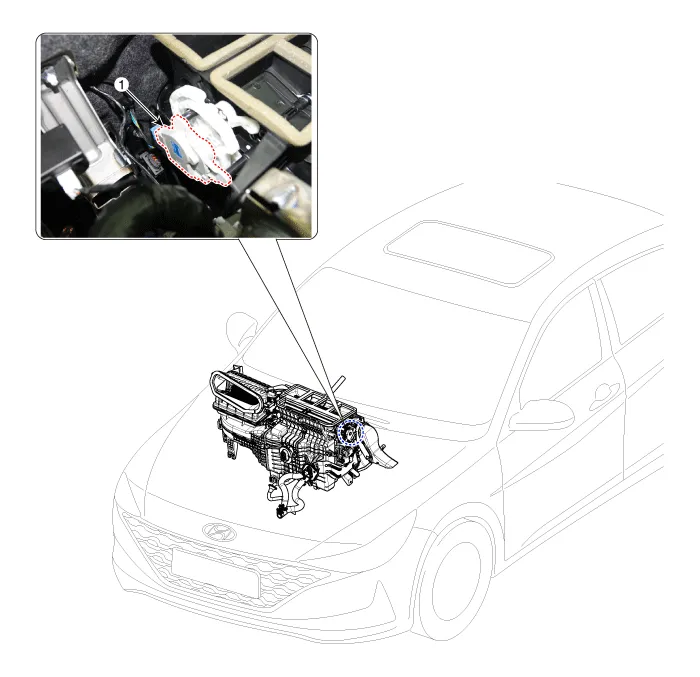
| 1. Mode control actuator |
Specifications
| Specifications |
|
Door position
|
Voltage (V)
|
Error detecting
|
| Max. cooling | 0.3 ± 0.15 | Low voltage : 0.1V or less |
| Max. heating | 4.7 ± 0.15 | High voltage : 4.9V or more |
Repair procedures
| Inspection |
| 1. | Turn the ignition switch OFF. |
| 2. | Disconnect the mode control actuator connector. |
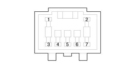
| 3. | Verify that the mode control actuator operates to the defrost mode when connecting 12V to terminal 3 and grounding terminal 7. Verify that the mode control actuator operates to the vent mode when connected in reverse.
|
| 4. | Connect the mode control actuator connector. |
| 5. | Turn the ignition switch ON. |
| 6. | Check the voltage between terminal 6 and 5. |
| 7. | If the measured voltage is not within specification, check the operation by replacing the existing mode control actuator with a new genuine part. After that, determine whether replacement of the temperature control actuator is required or not. |
| Replacement |
| 1. | Disconnect the negative (-) battery terminal. |
| 2. | Remove the main crash pad assembly. (Refer to Body (Interior and Exterior) - "Main Crash Pad Assembly") |
| 3. | Disconnect the connector (A) and then remove the mode control actuator (B) after loosening the mounting screws.
|
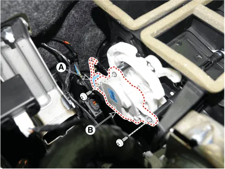
| 4. | To install, reverse the removal procedure. |
Description and operation DescriptionThe temperature control actuator is located at the heater unit. It regulates the temperature by the procedure as follows.
Description and operation DescriptionThe auto defogging sensor is installed on front window glass. The sensor judges and sends signal if moisture occurs to blow out wind for defogging.
Other information:
Hyundai Elantra (CN7) 2021-2025 Service Manual: Repair procedures
Refrigerant System Service Basics (R-134a)Refrigerant Recovery Use only service equipment that is U.L-listed and is certified to meet the requirements of SAE J2210 to remove HFC-134a(R-134a) from the air conditioning system. • Air conditioning refrigerant or lubricant vapor can irritate your eyes, nose, or
Hyundai Elantra (CN7) 2021-2025 Service Manual: Parking Distance Warning (PDW)
Description and operation Description• PDW consists of 8 sensors (front : 4 units, rear : 4 units) that are used to detect obstacles and transmit the result in three separate warning levels, the first, second and third to IBU via LIN communication.
Categories
- Manuals Home
- Hyundai Elantra Owners Manual
- Hyundai Elantra Service Manual
- Maintenance
- Suspension System
- Integrated Thermal Management Module (ITM)
- New on site
- Most important about car
