Hyundai Elantra (CN7): Body Electrical System / Power Door Locks
Components and components location
| Component Location |
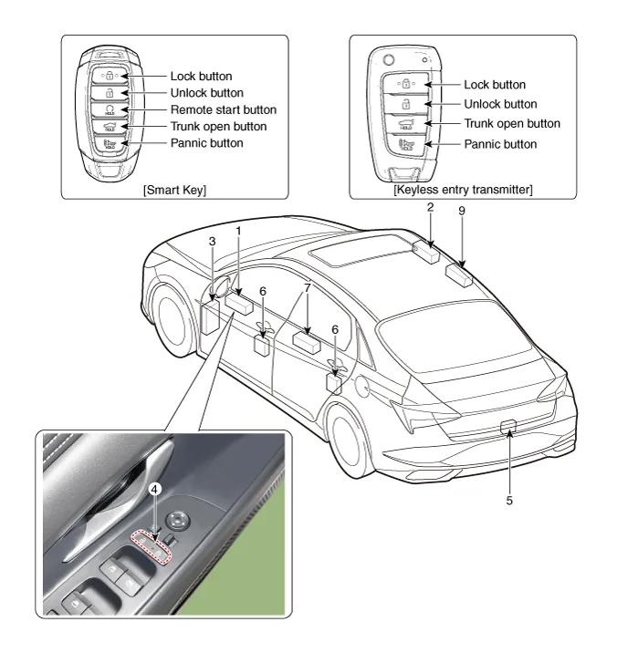
| 1. DDM (Driver Door Module) 2. ADM (Assist Door Module) 3. Integrated Central Control Unit (ICU) 4. Door lock knob 5. Trunk lid actuator | 6. Door latch module 7. Door lock/unlock switch 8. RLDM (Rear Left Door Module) 9. RRDM (Rear Right Door Module) |
Power Door Lock Module
Components and components location
| Conponents |
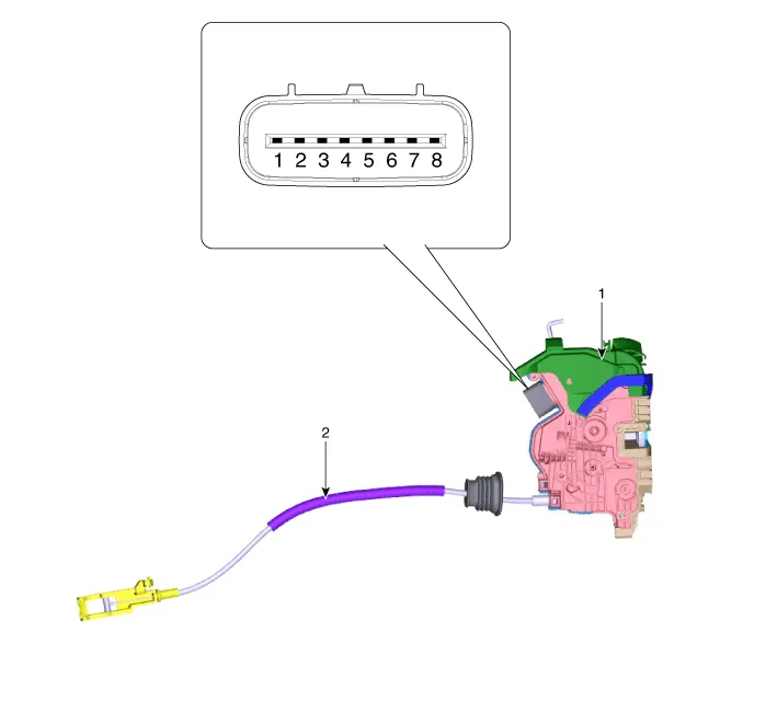
| 1. Door latch assembly | 2. Door latch cable |
Repair procedures
| Inspection |
|

| 1. | Remove the front door trim. (Refer to Body - "Front Door Trim") |
| 2. | Remove the front door module. (Refer to Body - "Front Door Module") |
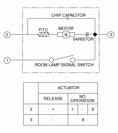
| 3. | Disconnect the connector from the actuator.
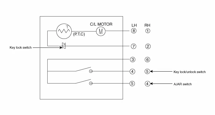
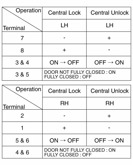
| |||||||||||||||||||||||||||||
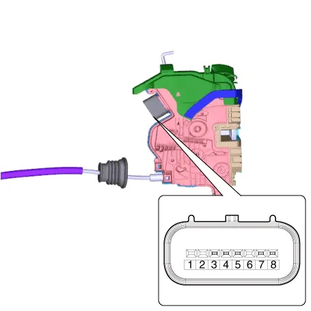
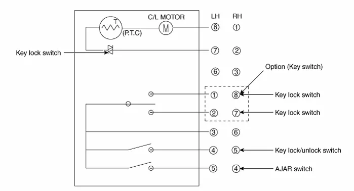
| 4. | Check actuator operation by connecting power and ground according to the table. To prevent damage to the actuator, apply battery voltage only momentarily.
|

| 1. | Remove the rear door trim. (Refer to Body - "Rear Door Trim") |
| 2. | Remove the rear door module. (Refer to Body - "Rear Door Module") |
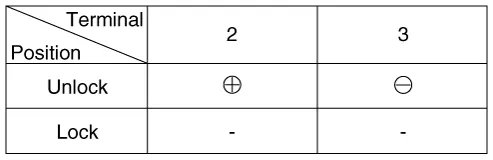
| 3. | Disconnect the connectors from the actuator.
| |||||||||||||||||||||||||||||
| 4. | Check actuator operation by connecting power and ground according to the table. To prevent damage to the actuator, apply battery voltage only momentarily.
|
| 1. | Remove the trunk lid trim. (Refer to Body - "Trunk Lid Trim") |
| 2. | Disconnect the connector from the actuator
|
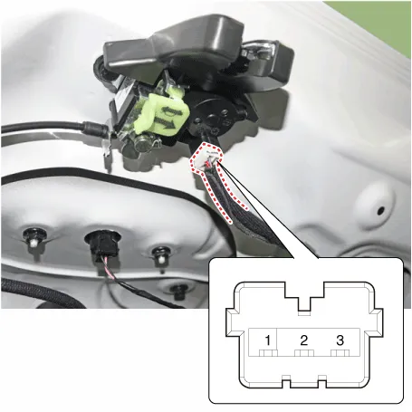
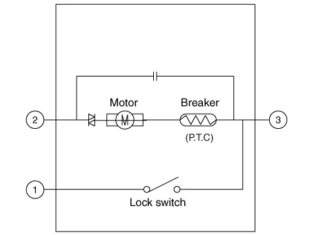
| 3. | Check actuator operation by connecting power and ground according to the table. To prevent damage to the actuator, apply battery voltage only momentarily.
|
| 4. | Checking the trunk of the vehicle power option power refers to the trunk module. |
Power Door Lock Switch
Repair procedures
| Inspection |
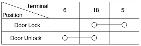
| 1. | Check for continuity between the terminals. If there is an abnormality, replace the switch.
|

| Removal |
|
| 1. | Disconnect the negative (-) battery terminal. |
| 2. | Remove the front door trim. (Refer to Body - "Front Door Trim") |
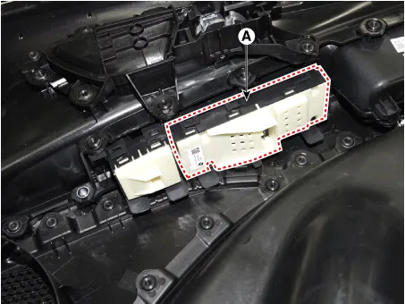
| 3. | Remove the power window switch assembly after disengaging the mounting clips.
|
| Installation |
| 1. | Install the power window switch assembly. |
| 2. | Install the front door trim after connect the connector. |
| 3. | Connect the negative (-) battery terminal. |
Description and operation Description Abbreviation Expalnation ACUAirbag Control UnitADMAssist Door ModuleB_CANBody Controller Area NetworkBCMBody Control ModuleBCWBlind-Spot Collision WarningC_CANChassis Controller Area NetworkCLUCluster ModuleDATCDual Automatic Temp ControlDDMDriver Door ModuleESCElectronic Stability ProgramEMSEngine Management SystemLKASLane Keeping Assist SystemM_CANMulti media Controller Area NetworkMDPSMotor Driven Power SteeringP_CANPowertrain Controller Area NetworkPSMPower Seat ModuleSASSteering Angle SensorSJBSmart Junction BlockSMKSmart Key UnitPDWParking Distance WarningTCUTransmission Control UnitTPMSTire Pressure Monitoring SystemVDCVehicle Dynamic ControlTMUTelematics SystemABSAnti-lock Brake SystemCluster Variant CodingAs we have more options (ESC, MDPS, SCC, etc.
Other information:
Hyundai Elantra (CN7) 2021-2026 Service Manual: Troubleshooting
TroubleshootingProblem Symptoms TableBefore replacing or repairing air conditioning components, first determine if the malfunction is due to the refrigerant charge, air flow or compressor.Use the table below to help you find the cause of the problem. The numbers indicate the priority of the likely cause of the problem.
Hyundai Elantra (CN7) 2021-2026 Service Manual: Description and operation
DescriptionRear Corner Radar is a system that measures the relative speed and distance from the following vehicles by using two electromagnetic wave radar sensors attached to the rear bumper, and detects any vehicle within the blind spot zone and gives off alarm.
Categories
- Manuals Home
- Hyundai Elantra Owners Manual
- Hyundai Elantra Service Manual
- Front Bumper
- Drive Mode
- Engine Control / Fuel System
- New on site
- Most important about car
