Hyundai Elantra (CN7): Body (Interior and Exterior) / Rear Bumper
Components and components location
| Component Location |
[General type]
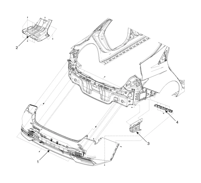
| 1. Rear bumper assembly 2. Rear bumper under cover [LH] | 3. Rear bumper under cover [RH] 4. Rear bumper side bracket |
[N Line]
| 1. Rear bumper assembly 2. Rear bumper side bracket 3. Rear bumper under cover [LH] | 4. Rear bumper under cover [CTR] 5. Rear bumper under cover [RH] |
Rear Bumper Assembly
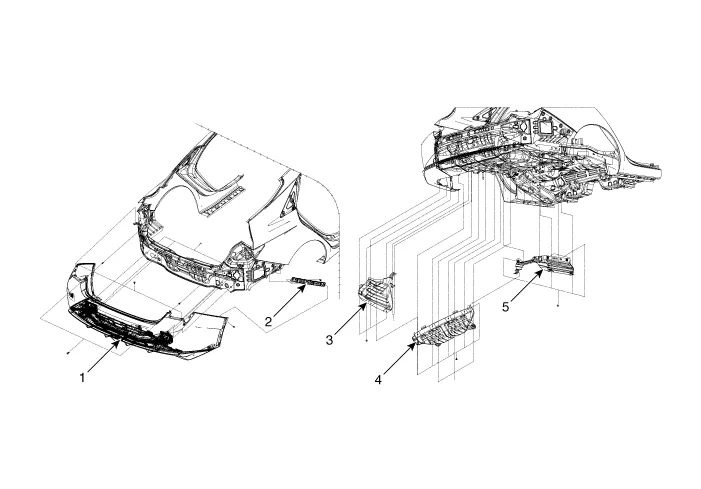
Components and components location
| Component Location |
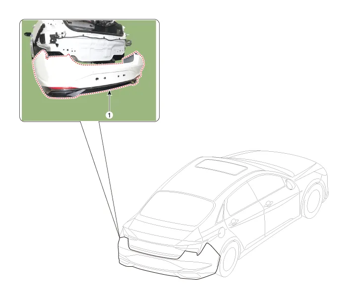
| 1. Rear bumper assembly |
Repair procedures
| Replacement |
|

|

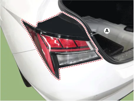
| 1. | Using a screwdriver or remover, remove the service cover (A).
|

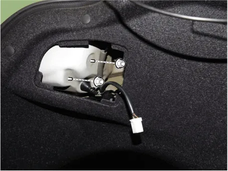
| 2. | Detach the rear combination lamp connector (A).
|

| 3. | Remove the rear combination mounting nuts and remove the rear combination lamp (A).
|
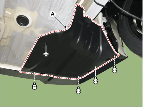
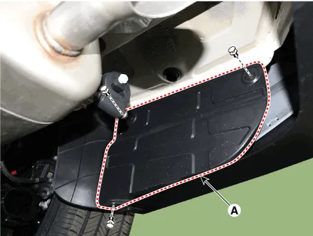
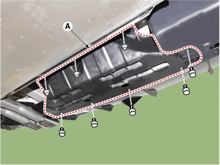
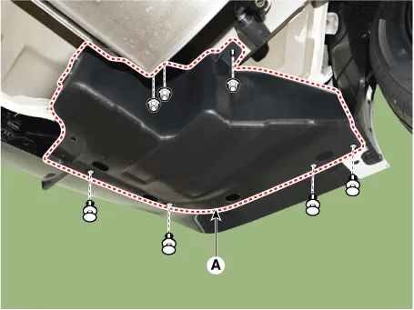
| 4. | Loosen the mounting nuts and clips, remove the rear bumper under cover (A). [General type] [LH]
[RH]
[N Line] [CTR]
[LH]
[RH]
|
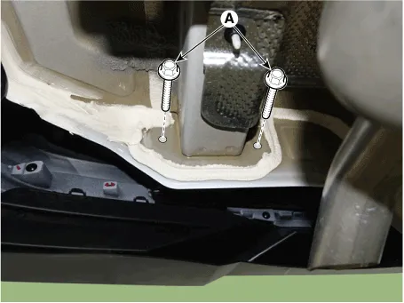
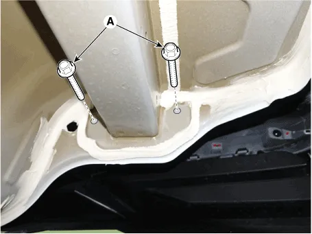
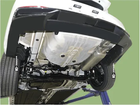
| 5. | Loosen the rear bumper assembly mounting bolts (A). [LH]
[RH]
|
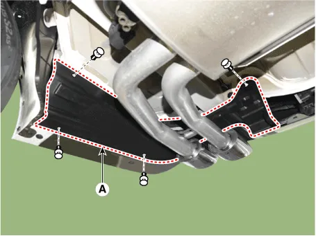
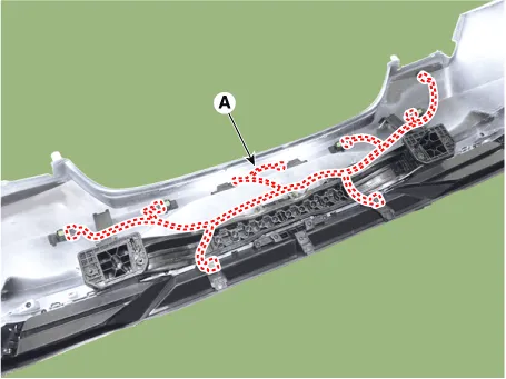
| 6. | Loosen the rear bumper lower mounting clips.
|
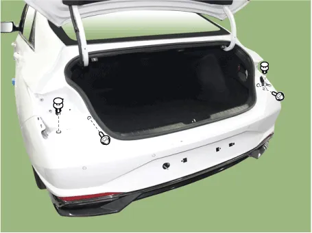
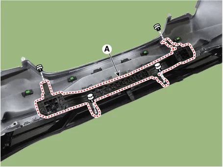
| 7. | Remove the rear bumper upper mounting clips and bolts.
|
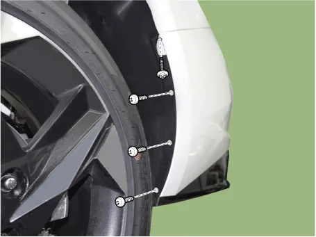
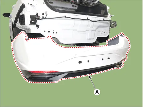
| 8. | Loosen the mounting screws on the side of rear bumper (A), detach the side part of rear bumper.
|

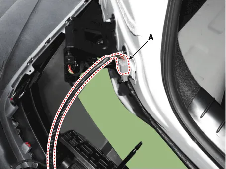
| 9. | Disconnect the rear bumper connector (A).
|
| 10. | Remove the rear bumper assembly (A).
|
| 11. | Install in the reverse order of removal.
|
Rear Bumper beam Assembly
Components and components location
| Component Location |
| 1. Rear bumper beam assembly |
Repair procedures
| Replacement |
|
|
| 1. | Remove the rear bumper assembly. (Refer to Rear Bumper - "Rear Bumper Assembly") |
| 2. | Press the lock pin, then detach the connector, remove the wiring hanes (A).
|
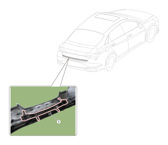
| 3. | Remove fixing clips, then remove the rear bumper beam assembly (A).
|
| 4. | Install in the reverse order of removal.
|

Components and components location Components[General type]1. Front bumper assembly2. Front bumper side bracket [LH]3. Front bumper side bracket [RH][N Line]1.
Other information:
Hyundai Elantra (CN7) 2021-2026 Service Manual: Description and operating principle
Description and OperationWireless Power Charger SystemDuring ACC or IG ON, battery voltage is supplied to the wireless power charger system to transmit an output of 5 W to mobile phone. Mobile phones certified with the wireless charging standard WPC (Qi 1.
Hyundai Elantra (CN7) 2021-2026 Service Manual: Evaporator Core
Repair procedures Replacement1.Disconnect the negative (-) battery terminal. 2.Remove the heater and blower assembly.(Refer to Heater - "Heater Unit") 3.Remove the heater core cover (A) after loosening the mounting screws.4.Pull out the evaporator core (A) from the heater unit.
Categories
- Manuals Home
- Hyundai Elantra Owners Manual
- Hyundai Elantra Service Manual
- Instrument Panel Overview
- Body (Interior and Exterior)
- Front Bumper
- New on site
- Most important about car

Copyright © 2026 www.helantra7.com - 0.0157