Hyundai Elantra (CN7): Advanced Driver Assistance System (ADAS) / Rear View Monitor (RVM)
Description and operation
| Description |
This system is a supplementary function only. It is the responsibility of the driver or always check the inside/ outside rear view mirror and the area behind the vehicle before and while backing up because there is a dead zone that can't see through the camera. |

Components and components location
| Component Location |
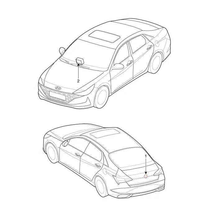
| 1. Rear view camera | 2. AVN monitor |
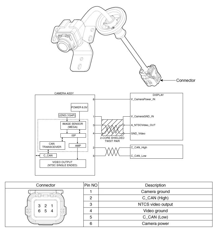
Schematic diagrams
| Circuit Diagram |
Repair procedures
| Removal |
| 1. | Disconnect the negative (-) battery terminal. |
| 2. | Remove the trunk trim. (Refer to Body - "Trunk Rid Trim") |
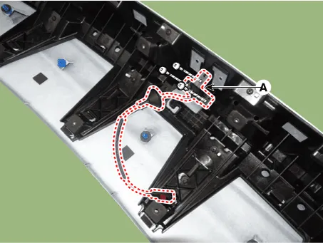
| 3. | Remove the trunk back panel. (Refer to Body - "Trunk back Panel") |
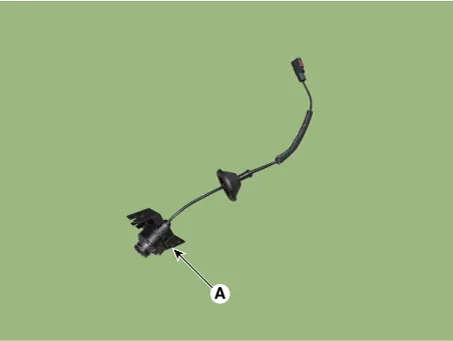
| 4. | Loosen the mounting screw and then remove the rear view camera (A).
|
| Installation |
| 1. | Install the rear view camera. |
| 2. | Install the and trunk back panel. |
| 3. | Install the and trunk rid trim. |
| 4. | Connect the negative (-) battery terminal. |
Description and operation Description• PDW consists of 8 sensors (front : 4 units, rear : 4 units) that are used to detect obstacles and transmit the result in three separate warning levels, the first, second and third to IBU via LIN communication.
Other information:
Hyundai Elantra (CN7) 2021-2026 Service Manual: Immobilizer Control Unit
Components and components location Components (1)With Smart KeyConnector Pin Information Pin no Connector A Connector B Connector C Connector D Connector E 1ESCL
Hyundai Elantra (CN7) 2021-2026 Service Manual: Temperature Control Actuator
Description and operation DescriptionThe temperature control actuator is located at the heater unit. It regulates the temperature by the procedure as follows. The signal from the control unit adjusts the position of the temperature door by operating the temperature switch.
Categories
- Manuals Home
- Hyundai Elantra Owners Manual
- Hyundai Elantra Service Manual
- Rear Seats
- Maintenance
- Vehicle Information
- New on site
- Most important about car
