Hyundai Elantra (CN7): Steering System / Repair procedures
| Service Adjustment Procedure |
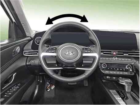
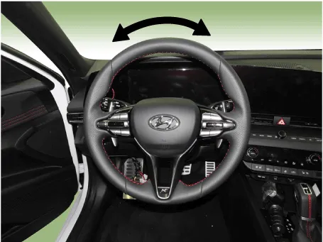
| 1. | Turn the steering wheel so that the front wheels can face straight ahead. |
| 2. | Measure the distance the steering wheel can be turned without moving the front wheels.
[G 1.6 MPI / LPI]
[G 1.6 T-GDI]
|
| 3. | If the play exceeds standard value, inspect the steering column, shaft, and linkages. |
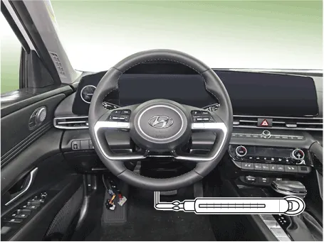
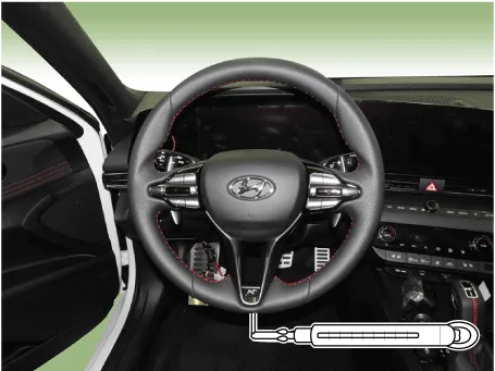
| 1. | Position the vehicle on a level surface and place the steering wheel in the straight ahead position. |
| 2. | While maintaining the engine speed at IDLE RPM, apply the spring balance to the end of the steering wheel and pull the scale to measure the force when the steering wheel starts moving.
[G 1.6 MPI / LPI]
[G 1.6 T-GDI]
|
| 3. | If the measured value exceeds standard value, inspect the steering gear box and MDPS system. |
Special Service Tools Tool (Number and Name) IIIustration Use 09568-1S100Ball joint removerSaperate the ball joint from the front alxe09563-IB000Small bearing removerRemove the small bearing09563-IB200Small bearing installerInstall the small bearing
Other information:
Hyundai Elantra (CN7) 2021-2026 Service Manual: Head Lamp Leveling Device
Components and components location Component Location1. Head lamp leveling actuator2. Head lamp leveling switch Head Lamp Leveling Switch Schematic diagrams Schematic Diagrams Repair procedures Replacement1.Disconnect the negative (-) battery terminal.
Hyundai Elantra (CN7) 2021-2026 Service Manual: Rear View Monitor (RVM)
Description and operation DescriptionRear view camera will activate when the backup light is ON with the ignition switch ON and the shift lever in the R position.This system is a supplemental system that shows behind the vehicle through the AV monitor or the ECM (Reverse Display Room Mirror) mirror while backing-up.
Categories
- Manuals Home
- Hyundai Elantra Owners Manual
- Hyundai Elantra Service Manual
- General Information
- Components and components location
- Rear Seats
- New on site
- Most important about car
