Hyundai Elantra: Integrated Body Control Unit (IBU) / Repair procedures
Hyundai Elantra (CN7) 2021-2025 Service Manual / Body Electrical System / Integrated Body Control Unit (IBU) / Repair procedures
| Removal |
| 1. | Disconnect the negative (-) battery terminal. |
| 2. | Remove the glove box housing cover. (Refer to Body - "Glove Box Housing Cover") |
| 3. | Remove the IBU unit (A) after loosening mounting nuts.
|
| 4. | Remove the IBU after disconnecting IBU connectors.
|
| Installation |
| 1. | Connect the integrated body control module connector. |
| 2. | Install the integrated body control module. |
| 3. | Install the glove box housing cover. |
| 4. | Connect the negative (-) battery terminal. |
| Diagnosis With Diagnostic tool |
| 1. | In the body electrical system, failure can be quickly diagnosed by using the vehicle diagnostic system (Diagnostic tool).
|
| 2. | If diagnose the vehicle by Diagnostic tool, select "DTC Analysis" and "Vehicle".
|
| 3. | If check current status, select the "Data Analysis" and "Car model".
|
| 4. | Select the 'IBU_BCM' to search the current state of the input/output data.
|


Other information:
Hyundai Elantra (CN7) 2021-2025 Service Manual: Components and components location
Components 1. Rear torsion beam axle2. Rear torsion beam chassis bracket3. Rear axle..
Hyundai Elantra (CN7) 2021-2025 Service Manual: Troubleshooting
Troubleshooting Symptom Probable cause Remedy play in steeringLoose yoke plugRetightenLoose steering gear mounting boltsRetightenLoose or worn tie rod endRetighten or replace as necessarySteering wheel does not return properlyExcessive turning resistance of tie rod endReplaceYoke plug excessively tightAdjustTie rod an..
Categories
- Manuals Home
- 7th Gen Hyundai Elantra Owners Manual
- 7nd Gen Hyundai Elantra Service Manual
- Recommended Lubricants and Capacities
- Body Electrical System
- Engine Compartment
- Fuel gauge
- Dimensions, Engine specification, Bulb Wattage
Odometer
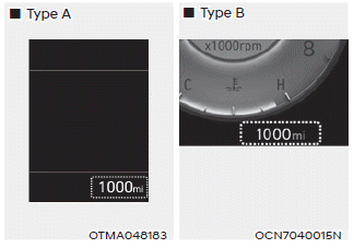
The odometer indicates the total distance that the vehicle has been driven and should be used to determine when periodic maintenance should be performed.

Copyright © 2025 www.helantra7.com