Hyundai Elantra (CN7): Ignition Switch Assembly / Repair procedures
Hyundai Elantra (CN7) 2021-2025 Service Manual / Body Electrical System / Ignition Switch Assembly / Repair procedures
| Replacement |
| 1. | Disconnect the negative (-) battery terminal. |
| 2. | Remove the crash pad lower panel. (Refer to Body - "Crash Pad") |
| 3. | Remove the steering column upper & Lower shroud. |
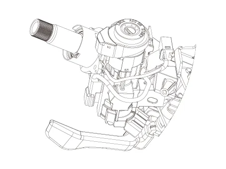
| 4. | Remove the ignition switch and disconnecting the Key Warning / immobilizer connector.
|
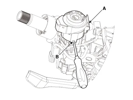
| 5. | If it is necessary to remove the key lock cylinder (A), remove the key lock cylinder (A) after pushing lock pin (B) with key ACC.
|
| 6. | Installation is the reverse of removal procedure. |
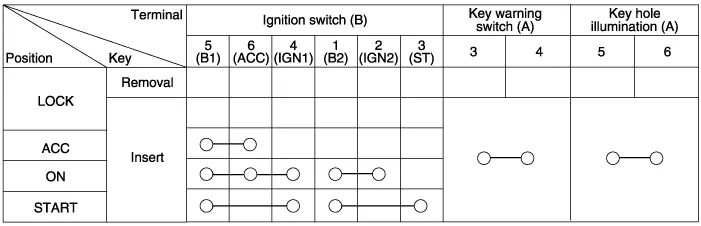
| Inspection |
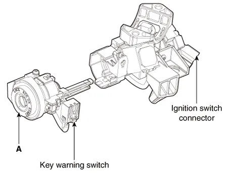
| 1. | Disconnect the ignition switch connector (A) and key warning switch connector (B) from under the steering column.
|

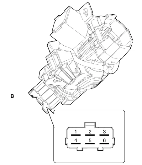
| 2. | Check for continuity between the terminals. |
| 3. | If continuity is not specified, replace the switch.
|
Other information:
Hyundai Elantra (CN7) 2021-2025 Service Manual: Front Radar Unit
Components and components location Components Location1. Front rader unit Specifications Specification Item Specification Power supply (V)12Operation voltage (V)9 - 16 Schematic diagrams Circuit DiagramTerminal function Pin No Te
Hyundai Elantra (CN7) 2021-2025 Service Manual: Troubleshooting
TroubleshootingDiagnosis with Diagnostic tool1.In the body electrical system, failure can be quickly diagnosed by using the vehicle diagnostic system (Diagnostic tool).The diagnostic system (Diagnostic tool) provides the following information.1)Fault Code Searching : Checking failure and code number (DTC)2)Data Analysis : Checking the system input/
Categories
- Manuals Home
- Hyundai Elantra Owners Manual
- Hyundai Elantra Service Manual
- Emergency situations
- Front Bumper Assembly
- Towing
- New on site
- Most important about car

Copyright © 2025 www.helantra7.com - 0.028