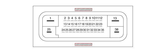
Hyundai Elantra (CN7): ESC (Electronic Stability Control) System / Schematic diagrams
| Terminal Function |
|
PIN No
|
Desciption
|
Current
| |
|
max
|
min
| ||
| 1 | Voltage supply for pump motor | 40A | 10 MΩ |
| 2 | Hazard switch | 1.2 mA | 250 MΩ |
| 3 | - | ||
| 4 | C-CAN HIGH | 100 mA | 250 MΩ |
| 5 | C-CAN LOW | 100 mA | 250 MΩ |
| 6 | |||
| 7 | P-CAN LOW | 100 mA | 250 MΩ |
| 8 | P-CAN High | 100 mA | 250 MΩ |
| 9 | Wheel speed sensor power voltage (RL) | 100 mA | 250 MΩ |
| 10 | Wheel speed sensor power voltage (RR) | 100 mA | 250 MΩ |
| 11 | Wheel speed sensor power voltage (FR) | 100 mA | 250 MΩ |
| 12 | Wheel speed sensor power voltage (FL) | 100 mA | 250 MΩ |
| 13 | Recirculation pump ground | 40A | 10 MΩ |
| 14 | - | ||
| 15 | Clutch Switch (MT Only) | 1.2 mA | 250 MΩ |
| 16 | DBC Switch | 1.2 mA | 250 MΩ |
| 17 | ESP Switch | 1.2 mA | 250 MΩ |
| 18 | - | ||
| 19 | Parking brake switch | 1.2 mA | 250 MΩ |
| 20 | - | ||
| 21 | Wheel speed sensor ground (RL) | 40 mA | 250 MΩ |
| 22 | Wheel speed sensor ground (RR) | 40 mA | 250 MΩ |
| 23 | Wheel speed sensor ground (FR) | 40 mA | 250 MΩ |
| 24 | Wheel speed sensor ground (FL) | 40 mA | 250 MΩ |
| 25 | Voltage supply for solenoid valves | 30A | 10 MΩ |
| 26 | - | ||
| 27 | - | ||
| 28 | - | ||
| 29 | - | ||
| 30 | Brake lamp switch | 1.2 mA | 250 MΩ |
| 31 | - | ||
| 32 | IGN 1 | 10mA | 50MΩ |
| 33 | - | ||
| 34 | HAC / BLA signal output | 1.2 mA | 250 MΩ |
| 35 | ESS signal output | 1.2 mA | 250 MΩ |
| 36 | - | ||
| 37 | Wheel speed sensor output (FR) | 50 mA | 250 MΩ |
| 38 | Ground for solenoid valves and ECU | 30A | 10 MΩ |

|
PIN No
|
Desciption
|
Current
|
Permit resistance
|
| 1 | Voltage supply for pump motor | 60A | 10 MΩ |
| 2 | RR EPB motor power | 15A | 10 MΩ |
| 3 | RR EPB motor ground | 15A | 10 MΩ |
| 4 | - | - | - |
| 4 | Clutch stroke sensor signal | - | - |
| 5 | Local CAN High | 40A | 250 MΩ |
| 6 | Electric parking brake signal 1 | 20 mA | 250 MΩ |
| 7 | Electric parking brake signal 2 | 20 mA | 250 MΩ |
| 8 | Electric parking brake signal 3 | 20 mA | 250 MΩ |
| 9 | Electric parking brake signal 4 | 20 mA | 250 MΩ |
| 10 | - | - | - |
| 11 | - | - | - |
| 12 | RL EPB motor ground | 15A | 10 MΩ |
| 13 | RL EPB motor power | 15A | 10 MΩ |
| 14 | Valves & ECU ground | 40A | 10 MΩ |
| 15 | DBC switch signal | 1.2 mA | 250 MΩ |
| 16 | - | ||
| 17 | ESP OFF switch signal | 1.2 mA | 250 MΩ |
| 18 | N Signal | 100 mA | 250 MΩ |
| 19 | Local CAN High | 100 mA | 250 MΩ |
| 20 | Local CAN Low | 100 mA | 250 MΩ |
| 21 | - | ||
| 22 | P-CAN LOW | 100 mA | 250 MΩ |
| 23 | P-CAN High | 100 mA | 250 MΩ |
| 24 | - | ||
| 25 | Wheel speed sensor supply voltage (RL) | 150 mA | 250 MΩ |
| 26 | Wheel speed sensor supply voltage (RR) | 150 mA | 250 MΩ |
| 27 | Wheel speed sensor supply voltage (FR) | 150 mA | 250 MΩ |
| 28 | Wheel speed sensor supply voltage (FL) | 150 mA | 250 MΩ |
| 29 | - | ||
| 30 | Voltage supply for solenoid valves | 40A | 10 MΩ |
| 31 | - | ||
| 32 | - | ||
| 33 | - | ||
| 34 | Auto holding ON/OFF switch signal | 1.2 mA | 250 MΩ |
| 35 | Brake light switch | 1.2 mA | 250 MΩ |
| 36 | HAC / BLA signal output | 1.2 mA | 250 MΩ |
| 37 | IGN 1 | 10 mA | 50 MΩ |
| 38 | ESS signal output | 1.2 mA | 250 MΩ |
| 39 | - | ||
| 40 | - | ||
| 41 | Wheel speed sensor ground (RL) | 40 mA | 250 MΩ |
| 42 | Wheel speed sensor ground (RR) | 40 mA | 250 MΩ |
| 43 | Wheel speed sensor ground (FR) | 40 mA | 250 MΩ |
| 44 | Wheel speed sensor ground (FL) | 40 mA | 250 MΩ |
| 45 | Wheel speed sensor power (FR) | 50 mA | 250 MΩ |
| 46 | Recirculation pump ground | 60A | 10 MΩ |
Failure Diagnosis1.In principle, ESP and TCS controls are prohibited in case of ABS failure.2.When ESP or TCS fails, only the failed system control is prohibited.
Components and components location Components[LHD]1. Front - right (FR)2. Rear - left (RL)3. Rear - right (RR)4. Front - left (FL)5. MC26. MC17. ABS control module (HECU)8.
Other information:
Hyundai Elantra (CN7) 2021-2025 Service Manual: Heater Control Unit
Components and components location Component Location1. Heater control unitComponents[Connector A] Pin No Function Pin No Function 1Mode control actuator (Feedback)21Mode control actuator (Vent)2Intake actuator (Feedback)22Mode control actu
Hyundai Elantra (CN7) 2021-2025 Service Manual: Smart Cruise Control (SCC) Switch
Schematic diagrams Circuit DiagramTRIP / SCC / LFA Repair procedures Inspection1.Check for resistance between terminals in each switch position (LH).[LH : Audio + Hands free] Switch Resistance (±5%) SEEK Up430 ΩSEEK Down1.
Categories
- Manuals Home
- Hyundai Elantra Owners Manual
- Hyundai Elantra Service Manual
- Front Bumper
- Integrated Thermal Management Module (ITM)
- Emergency situations
- New on site
- Most important about car
