Hyundai Elantra (CN7): Starting System / Starter Relay
Repair procedures
| Inspection |
| 1. | Turn ignition switch OFF and disconnect the negative (-) battery cable. |
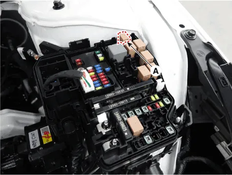
| 2. | Remove the fuse box cover. |
| 3. | Remove the starter relay (A).
|
| 4. | Using an ohmmeter, check that there is continuity between each terminal.
|
| 5. | Apply 12V to terminal 85 and ground to terminal 86. Check for continuity between terminals 30 and 87.
|
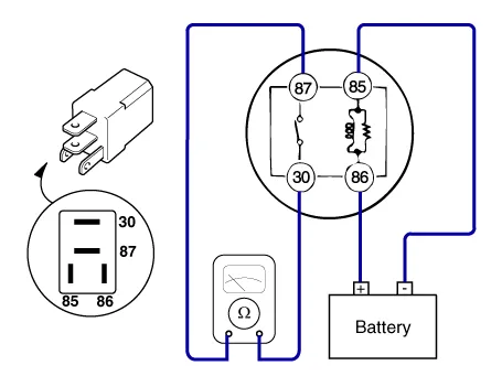
| 6. | If there is no continuity, replace the starter relay. |
| 7. | Install the starter relay. |
| 8. | Install the fuse box cover. |
Description and operation DescriptionThe starting system includes the battery, starter, solenoid switch, ignition switch, inhibitor switch, ignition lock switch, connection wires and the battery cable.
Other information:
Hyundai Elantra (CN7) 2021-2025 Service Manual: General safety information and caution
Instructions (R-134a)When Handling Refrigerant1.R-134a liquid refrigerant is highly volatile. A drop on the skin of your hand could result in localized frostbite. When handling the refrigerant, be sure to wear gloves. 2.It is standard practice to wear goggles or glasses to protect your eyes, and gloves to protect your hands.
Hyundai Elantra (CN7) 2021-2025 Service Manual: Parking Collision-Avoidance Assist (PCA)
Components and components location Components and Components Location Schematic diagrams Schematic DiagramsParking Collision-Avoidance Assist (PCA) Ultrasonic sensorParking Collision-Avoidance Assist (PCA) Rear view camera Repair procedures RemovalParking Collision-Avoidance Assist (PCA) Unit1.
Categories
- Manuals Home
- Hyundai Elantra Owners Manual
- Hyundai Elantra Service Manual
- Front Bumper
- Maintenance
- Rear Seats
- New on site
- Most important about car
