Hyundai Elantra (CN7): Tire Pressure Monitoring System / TPMS Sensor
Description and operation
| Description |
| 1. | Function
|
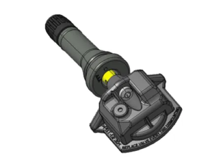
| 2. | Structure and features
|
| 3. | Mode
|
| • | After stopping or parking for more than 19 minutes, automatic learning function in every driving position is performed. |
| • | The sensor is converted to Parking Mode when stopped or parked for more than 15 minutes. When acceleration of over 4g (15-20km/h) is detected in Parking Mode, it is converted to First Block Mode. |
Repair procedures
| Removal |
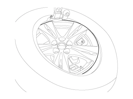
| 1. | Remove the wheel and tire. (Refer to Suspension System - "Wheel") |
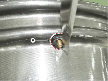
| 2. | Remove the screw with torx driver (A).
|

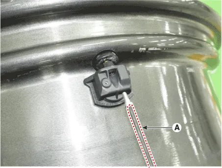
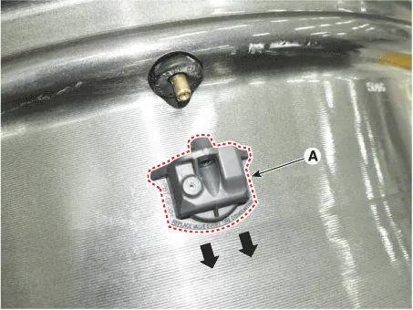
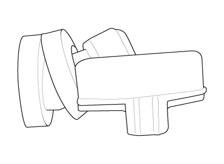
| 3. | Remove the sensor body (A) in the direction of the arrow.
|
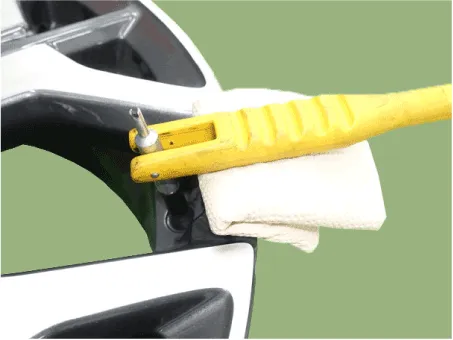
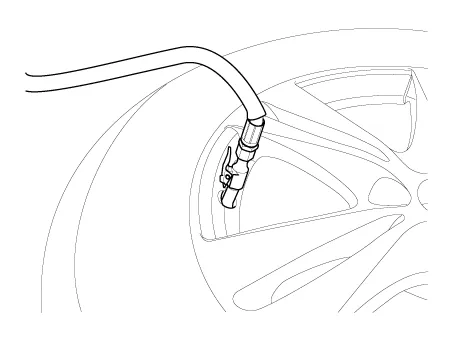
| 4. | Use the valve mounting tool to pull out the valve until it is entirely out of the lower hole.
|

| 5. | Apply lubricant to the surface of the new valve, and then mount it through the valve hole of the wheel.
|
| 6. | Apply soapy water or lubricant to the upper/lower bead section of the tire.
|

| 7. | To fit the bottom bead, position the sensor at the 5 o’clock position relative to the head on the tire changing machine
|
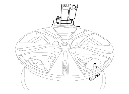
| 8. | Rotate the rim clockwise, and push down on the tire at the 3 o’clock position to fit bottom bead.
|
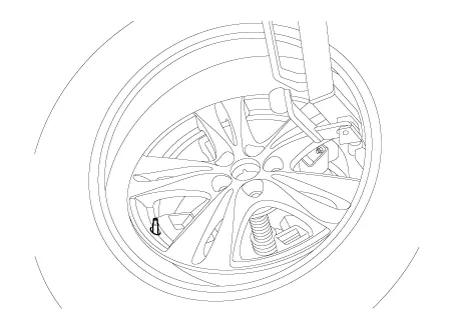
| 9. | Push down on the tire at the 3 o’clock position and rotate the rim clockwise to fit the top bead.
|
| 10. | Inflate the tire until beads seat.
|
| 11. | Adjust the tire pressure according to the recommended tire pressure for the vehicle.
|
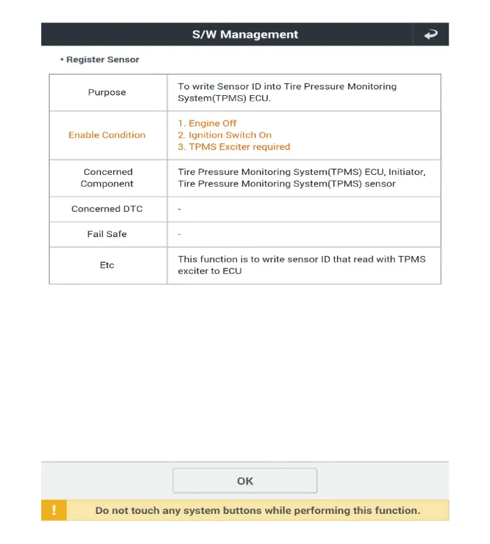
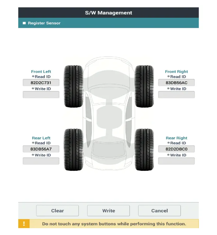
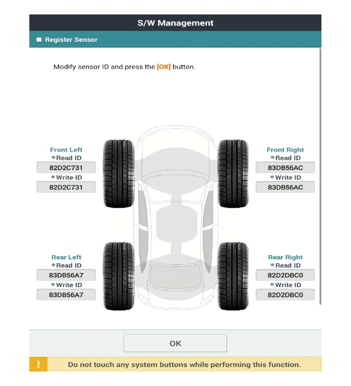
| 12. | If the TPMS sensor malfunctions, you must perform TPMS sensor learning. Replace any faulty sensors and perform TPMS sensor learning. |
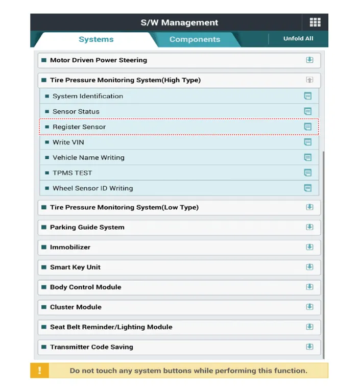
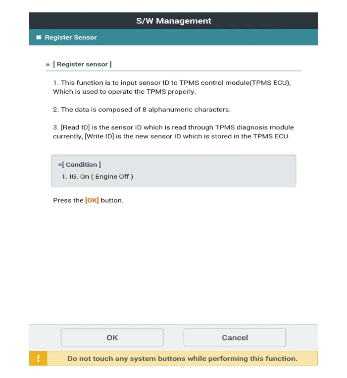
| Diagnostic Procedure Using a Diagnostic Instrument |
| 1. | Connect the diagnostic instrument to the self-diagnostic connector (16-pin) beneath the crash pad on the side of driver's seat, and then turn on the ignition to activate the diagnostic instrument. |
| 2. | In the GDS Vehicle Type Selection menu, select "Vehicle Type" and "TPMS" System, and then opt for "OK." |
|
|
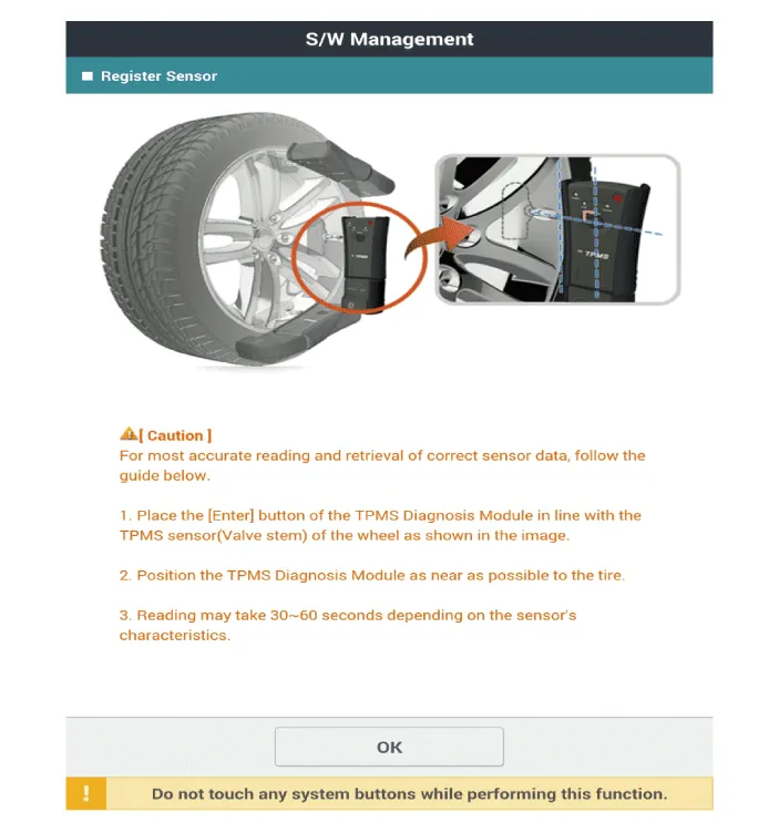
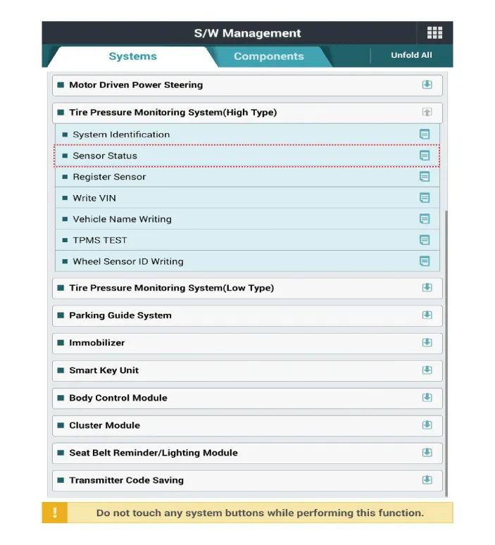
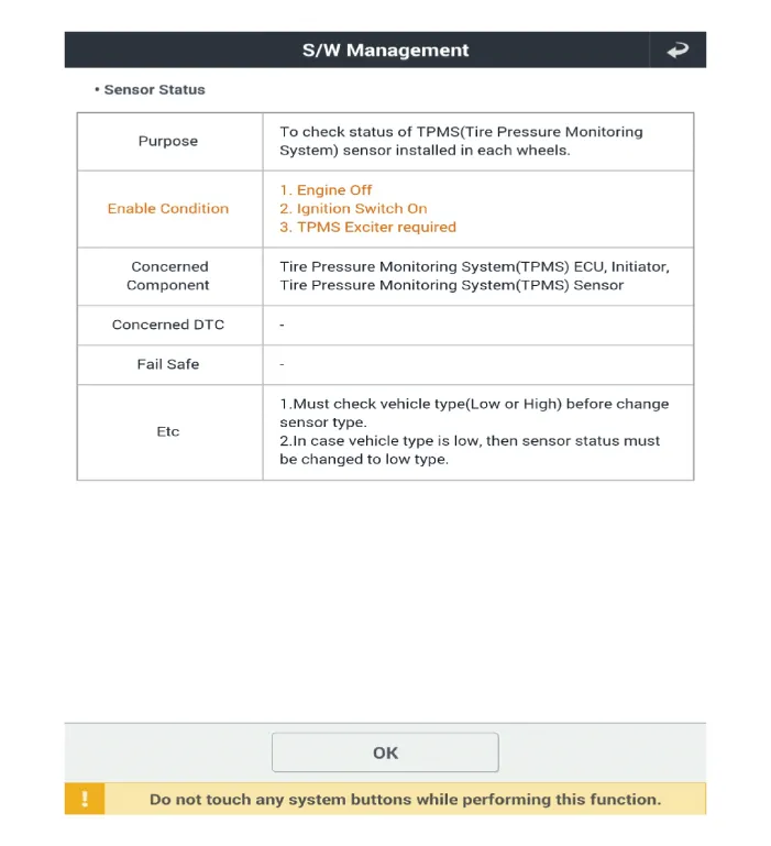
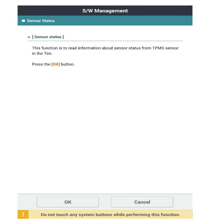
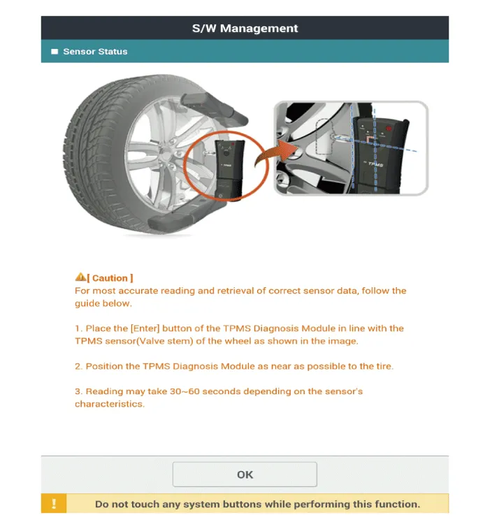
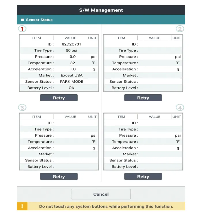
TPMS Inspection method
Description and operation DescriptionTPMS Receiver : BCM(body control module) integrated management1.Early state• Platform information and sensor ID are not input.
Other information:
Hyundai Elantra (CN7) 2021-2026 Service Manual: Condenser
Components and components location Components Location[General type]1. Condenser[N Line]1. Condenser Repair procedures Inspection1.Check the condenser fins for clogging and damage. If clogged, clean them with water, and blow them with compressed air.
Hyundai Elantra (CN7) 2021-2026 Service Manual: Warning Indicator
Components and components location Components1. BSD Indicator2. Side repeater lamp Repair procedures Inspection1.Disconnect the negative (-) battery terminal.2.Remove the front door trim.(Refer to Body - "Front door trim")3.Disconnect the power door mirror connector from the harness4.
Categories
- Manuals Home
- Hyundai Elantra Owners Manual
- Hyundai Elantra Service Manual
- Troubleshooting
- General Tightening Torque Table. General information
- Repair procedures
- New on site
- Most important about car
