Hyundai Elantra (CN7): Audio / Antenna
Repair procedures
| Inspection |
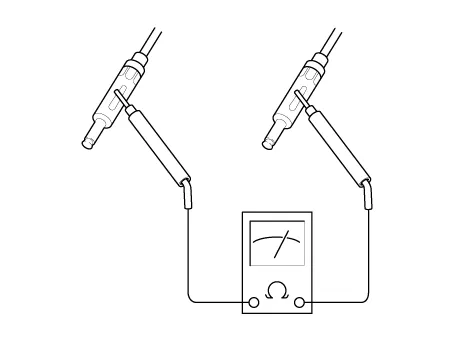
| 1. | Wrap aluminum foil (A) around the tip of the tester probe (B) as shown.
|
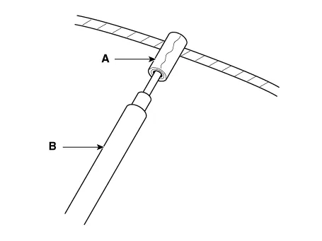
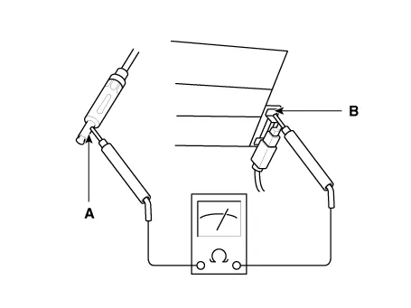
| 2. | Touch one tester probe to the glass antenna terminal (A) and move the other tester probe along the antenna wires to check that continuity exists.
|
|

| 1. | Lightly rub the area around the broken section (A) with fine steel wool, and then clean it with alcohol.
|
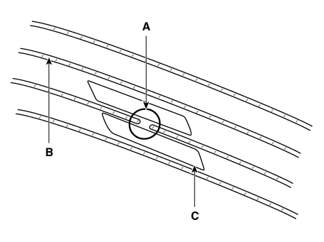
| 2. | Carefully mask above and below the broken portion of the glass antenna wire (B) with cellophane tape (C). |
| 3. | Using a small brush, apply a heavy coat of silver conductive paint (A) extending about 1/8″on both sides of the break. Allow 30 minutes to dry.
|
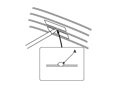
| 4. | Check for continuity in the repaired wire. |
| 5. | Apply a second coat of paint in the same way. Let it dry three hours before removing the tape. |
| 1. | Remove the rear pillar trim. (Refer to Body - "Rear Pillar Trim") |
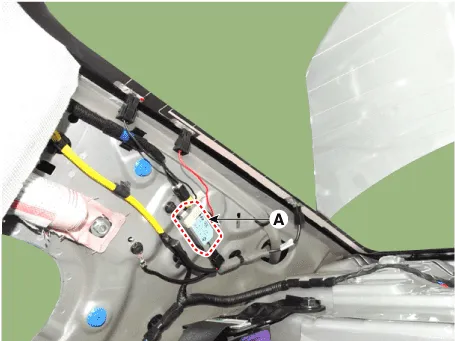
| 2. | Disconnect the antenna amp power connector from the glass antenna amp (A).
|
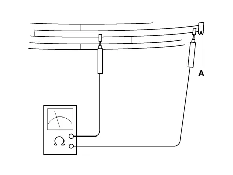
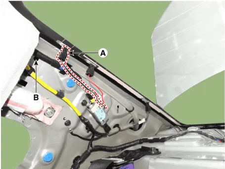
| 3. | Turn the radio ON. Measure the voltage between terminals of the antenna amp power connector (A) and body ground (B).
|

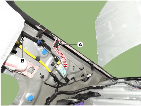
| 4. | Check for radio antenna wire resistance between terminals of the antenna connector (A) and body ground (B).
|
| 5. | Check the grid lines for continuity. |
| 6. | When a poor radio reception is not repaired through the above inspection methods, replace the amp. If the radio reception is still poor, check the radio cable for short and radio head unit for failure. |
| 1. | Check for continuity between the center poles of antenna cable.
|
| 2. | Check for continuity between the outer poles of antenna cable. There should be continuity.
|
| 3. | If there is no continuity, replace the antenna cable. |
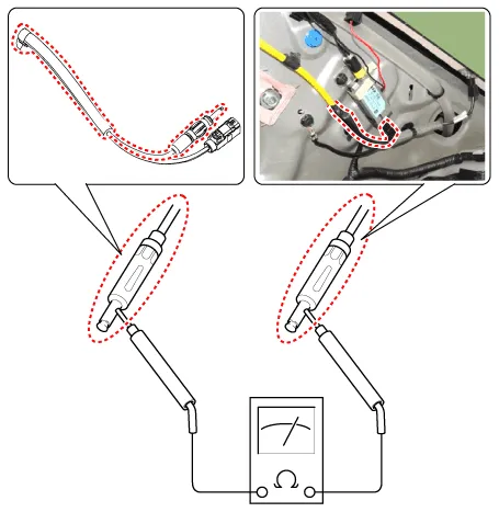
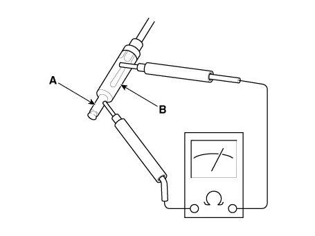
| 4. | Check for continuity between the center pole (A) of antenna cable and terminal of glass antenna (B). There should be continuity.
|
| 5. | If there is no continuity, replace the antenna amplifier. |
| 6. | Check for continuity between the center pole (A) and outer pole (B) of antenna cable. There should be no continuity.
|
| 7. | If there is continuity, replace the antenna cable. |
Repair procedures Inspection1.Troubleshooting for Speaker(1)Basic inspection of speakerInspect the sound from speaker after verifying that the speaker mounting screws is removed and the wiring connector is connected precisely to remove vibration transmitted from body trims and surrounding parts.
Components and components location Components1. Left Remote Control Switch (Audio + Bluetooth)2. Right Remote Control Switch (Cruise + Trip) Schematic diagrams Circuit Diagram[Without paddle shift][With paddle shift][Audio + B/Tooth][Audio + B/Tooth + Voice][Trip][Trip / Cruise][Trip + Cruise + LFA)[Trip + Cruise + LFA + MSLA)[Trip + Smart Cruise + LFA)[Trip + Smart Cruise + LFA + MSLA) Repair procedures Inspection1.
Other information:
Hyundai Elantra (CN7) 2021-2026 Service Manual: License Lamps
Repair procedures Removal1.Disconnect the negative (-) battery terminal.2.Push the lock pin (B) and remove the license lamp (A).3.Disconnect the license lamp connector (A).4.Replace the bulb (A).Installation1.Connect the license lamp connector.2.Install the license lamp.
Hyundai Elantra (CN7) 2021-2026 Service Manual: Intake Actuator
Description and operation DescriptionThe intake actuator is located at the blower unit. It regulates the intake door by a signal from the control unit. Pressing the intake selection switch will shift between recirculation and fresh air modes. Components and components location Components Location1.
Categories
- Manuals Home
- Hyundai Elantra Owners Manual
- Hyundai Elantra Service Manual
- Steering System
- Repair procedures
- Body (Interior and Exterior)
- New on site
- Most important about car
