Hyundai Elantra (CN7): Blower / Blower Unit
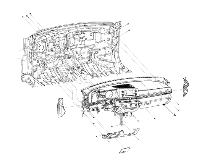
Components and components location
| Component Location |
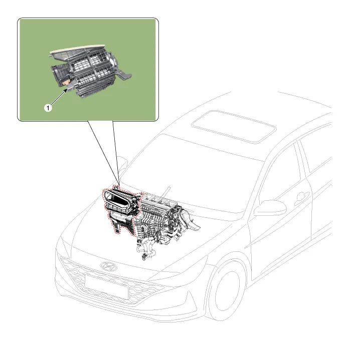
| 1. Blower unit assembly |
| Components |
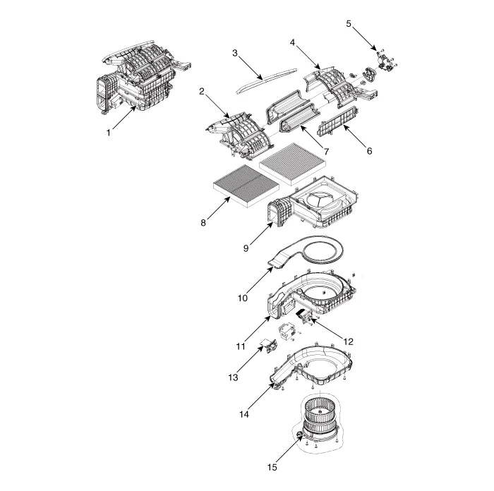
| 1. Blower unit assebmly 2. Blower upper cover [LH] 3. Duct seal 4. Blower upper cover [RH] 5. Intake actuator 6. Air filter cover 7. Intake door | 8. Air filter 9. Blower upper case 10. Blower plate 11. Blower lower case 12. Power mosfet 13. Resistor 14. Blower lower cover 15. Blower motor |
Repair procedures
| Replacement |
| 1. | Disconnect the negative (-) battery terminal. |
| 2. | Recover the refrigerant with a recovery / recycling / charging station. |
| 3. | When the engine is cool, drain the engine coolant from the radiator. (Refer to Engine Mechanical System - "Coolant") |
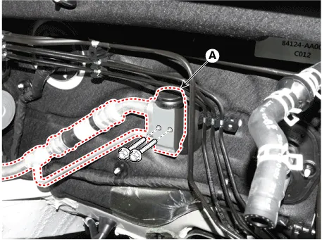
| 4. | Remove the bolts and the expansion valve (A) from the evaporator core.
|

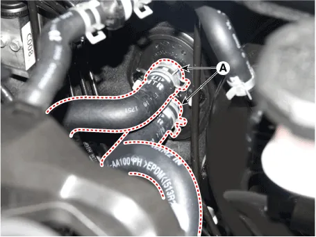
| 5. | Disconnect the heater hoses (A) from the heater unit.
|

| 6. | Remove the cowl top cover. (Refer to Body (Interior and Exterior) - "Cowl Top Cover") |
| 7. | Remove the battery. (Refer to Engine Electrical System - "Battery") |
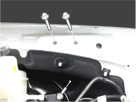
| 8. | Loosen the cowl cross member mounting bolts.
|
| 9. | Remove the front pillar trim. (Refer to Body (Interior and Exterior) - "Front Pillar Trim") |
| 10. | Remove the floor console assembly. (Refer to Body (Interior and Exterior) - "Floor Console Assembly") |
| 11. | Remove the shift lever assembly. (Refer to Automatic Transmission System - "Shift Lever") |
| 12. | Remove the cowl side trim. (Refer to Body (Interior and Exterior) - "Cowl Side Trim") |
| 13. | Remove the crash pad lower panel. (Refer to Body (Interior and Exterior) - "Crash Pad Lower Panel") |
| 14. | Remove the steering column shroud lower panel. (Refer to Body (Interior and Exterior) - "Steering Column Shroud Panel") |
| 15. | Remove the steering wheel. (Refer to Steering System - "Steering Wheel") |
| 16. | Remove the multifunction switch. (Refer to Body Electrical System - "Multifunction Switch") |
| 17. | Lower the steering column after loosening the mounting bolts. (Refer to Steering System - "Steering Column and Shaft") |
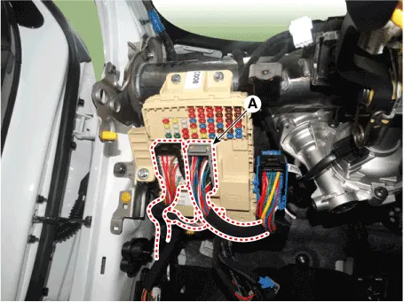
| 18. | Disconnect the junction box connectors (A).
|
| 19. | Disconnect the multi box connectors (A). [LH]
[RH]
|
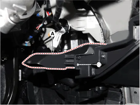
| 20. | Remove the center console duct (A).
|
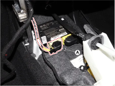
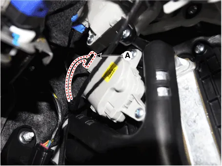
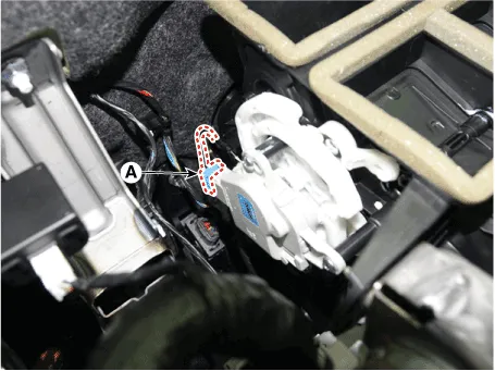
| 21. | Disconnect the airbag control module (SRSCM) connector (A).
|
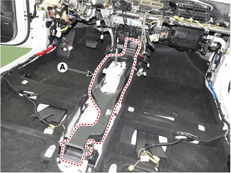
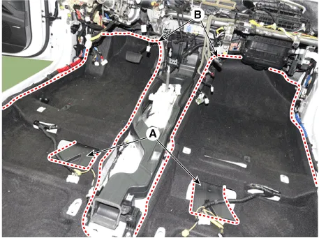
| 22. | Remove the rear air duct (A) and separate the floor carpet (B) to obtain space for removing the rear heating duct.
|
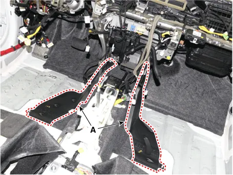
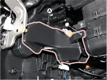
| 23. | Remove the front air duct (A).
|
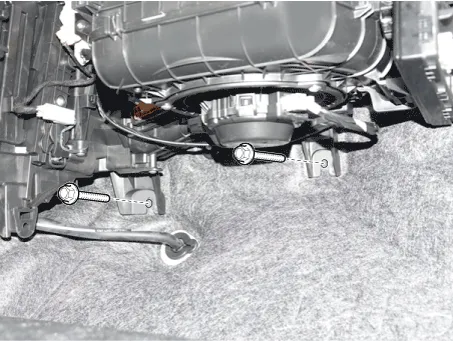
| 24. | Loosen the cowl blower unit mounting bolts.
|
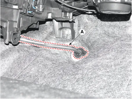
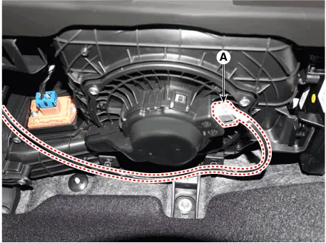
| 25. | Remove the drain hose (A).
|
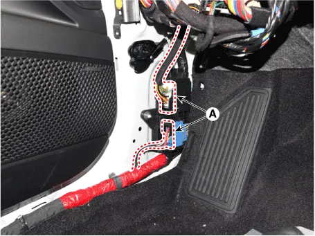
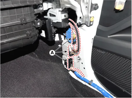
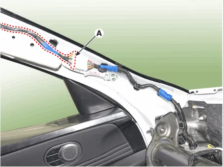
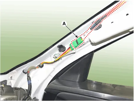
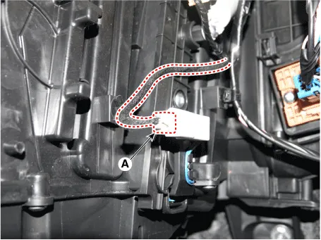
| 26. | Disconnect the connectors (A) and the mounting clips in the front pillar. [LH]
[RH]
|
| 27. | After loosening the bolts and nuts remove the main crash pad and cowl cross bar assembly (A) together.
|
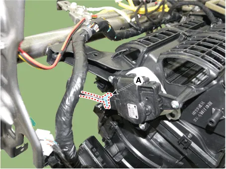
| 28. | Disconnect the heater & blower unit connectors. [Driver
[Passenger's side]
|
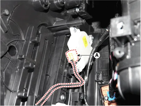
| 29. | Loosen the heater & blower unit mounting bolt.
|

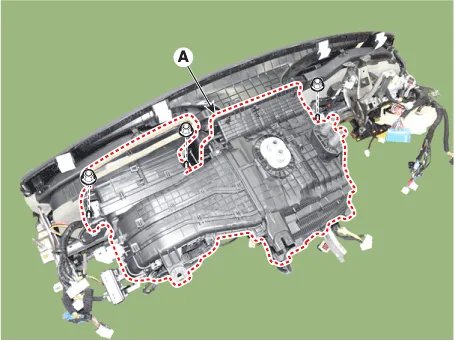
| 30. | Remove the heater and blower unit (A) from the crash pad after loosening the mounting nuts.
|
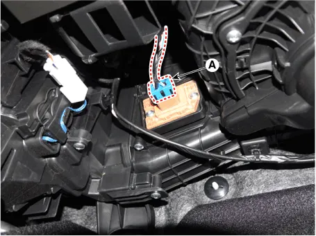
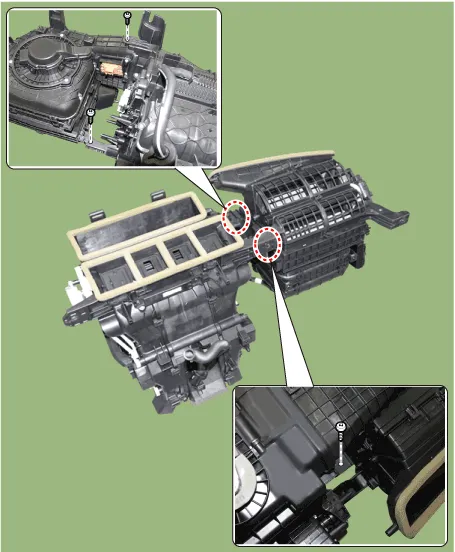
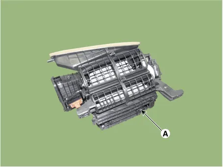
| 31. | Separate the blower unit (A) from the heater & blower unit assembly after loosening the screws.
|
| 32. | To install, reverse the removal procedure. |
Repair procedures Inspection1.Connect the battery voltage and check the blower motor rotation.Replacement1.Disconnect the negative (-) battery terminal.
Other information:
Hyundai Elantra (CN7) 2021-2026 Service Manual: Description and operation
Description and OperationBlcok Diagram • This system monitors the driving situations through the radar and the camera. Thus, for a situation out of the sensing range, the system may not normally operate. The System may be limited when : • The radar sensor or camer
Hyundai Elantra (CN7) 2021-2026 Service Manual: Repair procedures
Inspection1.Check for resistance between terminals in each switch position (LH).[LH : Audio + Hands free] Switch Resistance (±5%) SEEK Up430 ΩSEEK Down1.11 kΩMODE2.11 kΩMUTE3.11 kΩVolume (+)4.
Categories
- Manuals Home
- Hyundai Elantra Owners Manual
- Hyundai Elantra Service Manual
- Engine Mechanical System
- Body Electrical System
- Instrument Cluster
- New on site
- Most important about car
