Hyundai Elantra (CN7): Seat Electrical / Air Ventilation Seat
Components and components location
| Component Location |
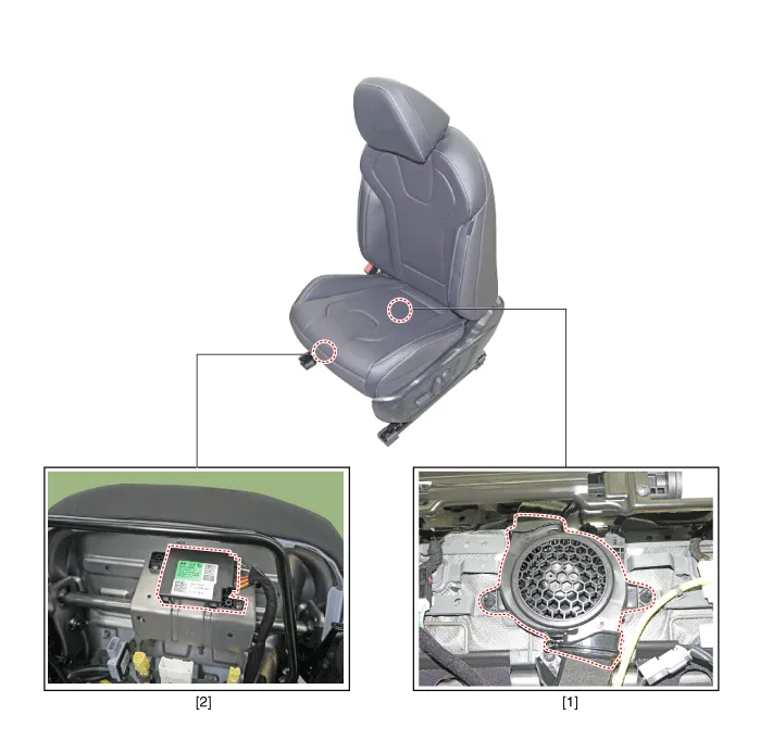
| 1. Ventilation seat blower | 2.Ventilation seat unit |
Schematic diagrams
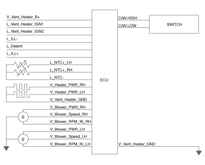
| Circuit Diagram |
|
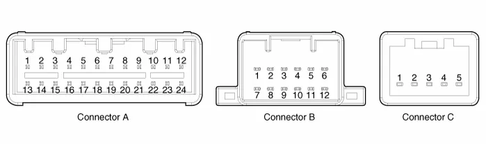
Pin no
|
Connector A
|
Connector B
|
Connector C
|
| 1 | Ventilation seat unit IGN 1 | Ventilation heater power | blower ground |
| 2 | Driver blower power | Driver heater power | - |
| 3 | Driver blower spped | Passenger heater power | blower VSP |
| 4 | Driver RPM input | - | blower F/B |
| 5 | Illumination (+) | Driver heater ground | blower VCC |
| 6 | - | Driver ventilation heater ground | |
| 7 | CAN Low | Driver ventilation power | |
| 8 | CAN High | - | |
| 9 | - | - | |
| 10 | LIN | - | |
| 11 | - | Passenger heater ground | |
| 12 | Driver blower ground | Ventilation heater ground | |
| 13 | Ventilation seat unit IGN 1 | ||
| 14 | Passenger blower power | ||
| 15 | Passenger blower speed | ||
| 16 | Passenger blower RPM input | ||
| 17 | Illumination (-) | ||
| 18 | Detent | ||
| 19 | - | ||
| 20 | Driver NTC (+) | ||
| 21 | Passenger NTC (+) | ||
| 22 | Passenger NTC (-) | ||
| 23 | Driver NTC (-) | ||
| 24 | Passenger blower ground |
Repair procedures
| Removal |
| 1. | Disconnect the negative (-) battery terminal. |
| 2. | Remove the front seat. (Refer to Body - "Front Seat Assembly") |
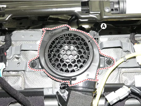
| 3. | Remove the blower duct (A).
|
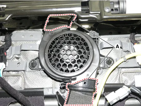
| 4. | Remove the blower FAN (A) after removing the screws.
|
| 1. | Disconnect the negative (-) battery terminal. |
| 2. | Remove the front seat. (Refer to Body - "Front seat Assembly") |
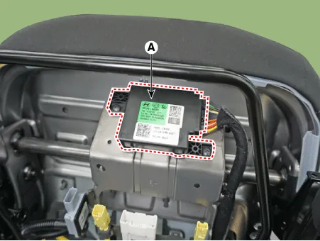
| 3. | Loosening the screws and then remove the ventilation seat unit (A) after disconnect the connectors.
|
| Installation |
| 1. | Install the blower fan. |
| 2. | Install the duct. |
| 3. | Install the front seat assembly. |
| 4. | Connect the negative (-) battery terminal. |
| 1. | Install the ventilation seat unit. |
| 2. | Install the front seat assembly. |
| 3. | Connect the negative (-) battery terminal. |
| Inspection |
| 1. | You can enter the diagnosis mode by turning the heater seat button on. |
| 2. | You can enter the diagnosis mode by referring to following description. |
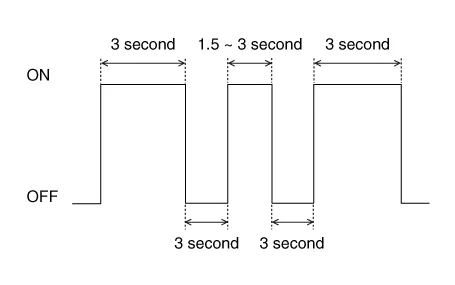
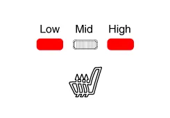
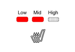
| 3. | Press the heating wire switch as shown below.
|
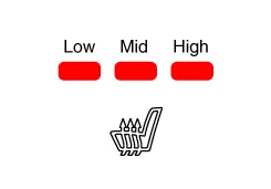
| 4. | When the vehicle enters the diagnostic mode, the three LEDs (Low, Mid, High) in the heating wire section blinks once for 0.5 seconds.
|

| 5. | After entering the diagnostic mode, check the LED status to identify the error.
|
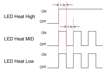
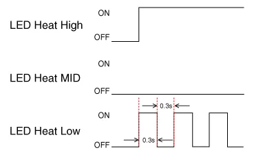

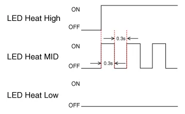
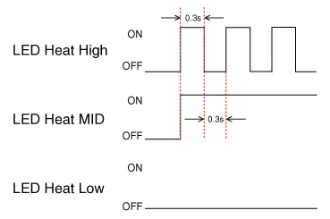
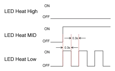
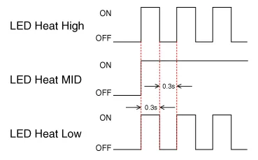
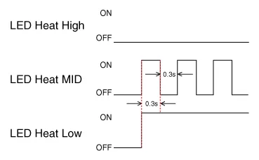
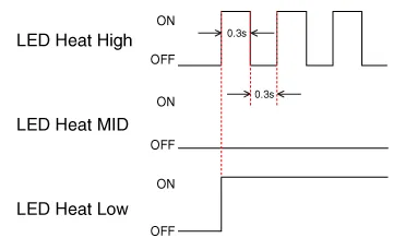
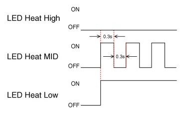
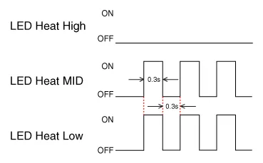
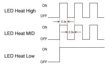
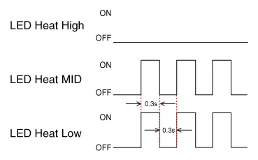
| 6. | You can check the malfunctioning by checking the blinking LED. |
| 7. | The failure data is recorded to the memory by the ventilation seat unit. |
| 8. | Press the heating wire seat switch on the passenger side for 5 seconds or more to make the LED blink four times and delete the failure data in the memory. |
| 9. | Pressing the IGN OFF button will end the diagnosis mode for the heater seat. |
| 10. | You can check whether the heating seat system works properly after turning the IGN ON. If you want to check the error code, you can refer to the procedure of 2 above. |
Components and components location Components1. Driver seat heater switch2. Passenger seat heater swtich3. 2nd seat heater switch Schematic diagrams Circuit DiagramManual Seat Heater SwitchConnector Pin Information[Connector A] Pin No Function Pin No Function 1Low (Register specifications)4Middle Low (Register specifications)2Common (Register specifications)5Middle High (Register specifications)3Ground (Register specifications)6High (Register specifications)[Connector B] Pin No Function Pin No Function 1Battery (+)21IGN22ISG B+22IGN13ILL+ (TAIL)23Blower IS (PWM specifications)4Sensor REF (+5V)24-5Mode control actuator (Feedback)25-6Temperature control actuator (Feedback)26-7Intake actuator (Feedback)27Blower Max.
Repair procedures Removal1.Disconnect the negative (-) battery terminal.2.Remove the front seat assembly.(Refer to Body - "Front Seat Assembly")3.Remove the seat back.
Other information:
Hyundai Elantra (CN7) 2021-2026 Service Manual: Wireless Power Charging Unit
Components and positions Components Circuit diagram Circuit Diagram Repair procedures Removal • Handling wireless charging system parts by wet hands may cause electric shock. 1.Disconnect the negative (-) battery terminal.
Hyundai Elantra (CN7) 2021-2026 Service Manual: Blower Motor
Repair procedures Inspection1.Connect the battery voltage and check the blower motor rotation.Replacement1.Disconnect the negative (-) battery terminal.2.Disconnect the blower motor connector (A) and then remove the blower motor (B) after loosening the screws.
Categories
- Manuals Home
- Hyundai Elantra Owners Manual
- Hyundai Elantra Service Manual
- Drive Mode
- Front Bumper
- Engine Mechanical System
- New on site
- Most important about car
