Hyundai Elantra (CN7): Seat Electrical / Seat Heater Switch
Components and components location
| Components |
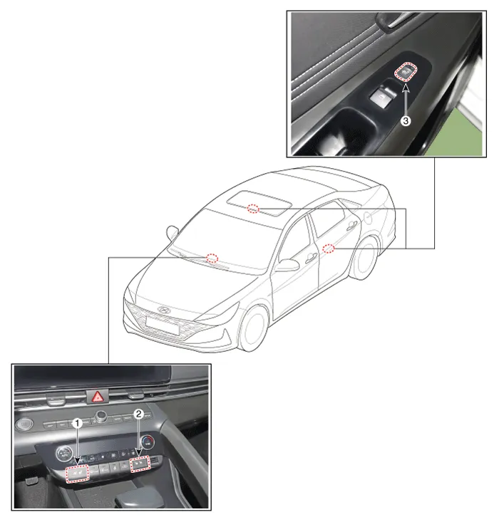
| 1. Driver seat heater switch 2. Passenger seat heater swtich | 3. 2nd seat heater switch |
Schematic diagrams
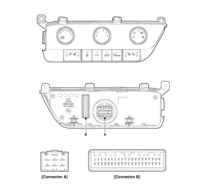
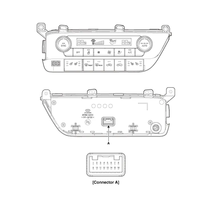
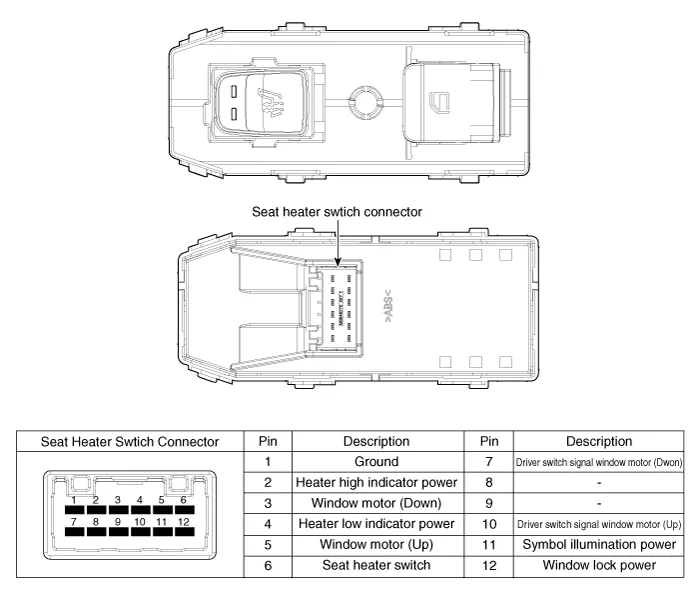
| Circuit Diagram |
|
Pin No
|
Function
|
Pin No
|
Function
|
| 1 | Low (Register specifications) | 4 | Middle Low (Register specifications) |
| 2 | Common (Register specifications) | 5 | Middle High (Register specifications) |
| 3 | Ground (Register specifications) | 6 | High (Register specifications) |
|
Pin No
|
Function
|
Pin No
|
Function
|
| 1 | Battery (+) | 21 | IGN2 |
| 2 | ISG B+ | 22 | IGN1 |
| 3 | ILL+ (TAIL) | 23 | Blower IS (PWM specifications) |
| 4 | Sensor REF (+5V) | 24 | - |
| 5 | Mode control actuator (Feedback) | 25 | - |
| 6 | Temperature control actuator (Feedback) | 26 | - |
| 7 | Intake actuator (Feedback) | 27 | Blower Max. On signal (Register specifications) |
| 8 | EVAP sensor (+) | 28 | - |
| 9 | AMB sensor (+) | 29 | PTC relay |
| 10 | Mode control actuator (Vent) | 30 | - |
| 11 | Mode control actuator (DEF) | 31 | - |
| 12 | Temperature control actuator (Cool) | 32 | - |
| 13 | Temperature control actuator (Warm) | 33 | P_CAN High |
| 14 | Intake actuator (FRE) | 34 | P_CAN Low |
| 15 | Intake actuator (REC) | 35 | Blower INH (PWM specifications) |
| 16 | HDT | 36 | Blower PWM (In) (PWM specifications) |
| 17 | - | 37 | ECV (+) |
| 18 | - | 38 | ECV (-) |
| 19 | Blower signal (On) (Register specifications) | 39 | Sensor ground |
| 20 | ILL- (RHEO) | 40 | Ground |
|
Pin No
|
Function
|
Pin No
|
Function
|
| 1 | Battery | 9 | IGN2 |
| 2 | ILL+ (TAIL) | 10 | ISG Battery (+) |
| 3 | - | 11 | IGN1 |
| 4 | LIN BUS | 12 | HTD |
| 5 | - | 13 | - |
| 6 | - | 14 | - |
| 7 | - | 15 | - |
| 8 | RHEO (ILL-) | 16 | Ground |
Repair procedures
| Removal |
| 1. | Disconnect the negative (-) battery terminal. |
| 2. | Remove heater & A/C control unt. (Refer to Heating, Ventilation and Air Conditioning - "Heater & A/C Control Unit (Manual") |
| 1. | Disconnect the negative (-) battery terminal. |
| 2. | Remove heater & A/C control unt. (Refer to Heating, Ventilation and Air Conditioning - "Heater & A/C Control Unit (DATC") |
| 1. | Disconnect the negative (-) battery terminal. |
| 2. | Remove the rear door window switch. (Refer to Power Windows - "Power Window Switch") |
| Installation |
| 1. | Install the heater & A/C control unt. |
| 2. | Connect the negative (-) battery terminal. |
| 1. | Install the rear door window switch. |
| 2. | Connect the negative (-) battery terminal. |
Components and components location Component Location[Front Seat Heater]1. Seat heater unit (Passenger only) 2. Seat cushion heater3. Seat back heater[Rear Seat Heater]1.
Components and components location Component Location[Front Ventilation Seat]1. Ventilation seat blower2.Ventilation seat unit Schematic diagrams Circuit DiagramConnector Pin Information Pin no Connector A Connector B Connector C 1Ventilation seat unit IGN 1 Ventilation heater power blower ground2Driver blower powerDriver heater power - 3Driver blower sppedPassenger heater power blower VSP4Driver RPM input- blower F/B5Illumination (+)Driver heater ground blower VCC6-Driver ventilation heater ground 7CAN LowDriver ventilation power8CAN High- 9- - 10LIN- 11- Passenger heater ground12Driver blower groundVentilation heater ground13Ventilation seat unit IGN 1 14Passenger blower power15Passenger blower speed16Passenger blower RPM input 17Illumination (-)18Detent19-20Driver NTC (+) 21Passenger NTC (+) 22Passenger NTC (-) 23Driver NTC (-) 24Passenger blower ground Repair procedures Removal[Ventilation Blower]1.
Other information:
Hyundai Elantra (CN7) 2021-2026 Service Manual: Heater Core
Repair procedures Replacement1.Disconnect the negative (-) battery terminal. 2.Remove the heater and blower assembly.(Refer to Heater - "Heater Unit") 3.Remove the heater core cover (A) after loosening the mounting screws.4.Pull out the heater core (A) from the heater unit.
Hyundai Elantra (CN7) 2021-2026 Service Manual: General safety information and caution
General Safety Information and Caution1.Be careful when driving the vehicle using the smart cruise control system as follows.(1)On curves or inclines/declines• The smart cruise control system may have limits to detect distance to the vehicle ahead due to road and traffic conditions.
Categories
- Manuals Home
- Hyundai Elantra Owners Manual
- Hyundai Elantra Service Manual
- Integrated Thermal Management Module (ITM)
- Suspension System
- Rear Seats
- New on site
- Most important about car
