Hyundai Elantra (CN7): Engine Control System / Ambient Temperature Sensor (ATS)
Description and operation
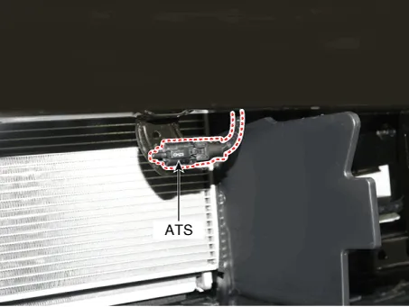
Ambient Temperature Sensor (ATS) is installed on the front-end module and senses the ambient temperature.
This sensor is exposed to the ambient air temperature in front of the radiator.
The ATS is a Negative Temperature Coefficient (NTC)-type sensor and its resistance is in inverse proportion to the temperature.
Specifications
Temperature [°C (°F)]
|
Resistance (kΩ)
|
-40 (-40)
| 841.2 - 1019.3
|
-20 (-4)
| 263.8 - 306.5
|
0 (32)
| 92.4 - 102.8
|
10 (50)
| 57.0 - 62.2
|
20 (68)
| 36.2 - 38.8
|
40 (104)
| 15.3 - 16.7
|
50 (122)
| 10.3 - 11.4
|
60 (140)
| 7.1 - 8.0
|
80 (176)
| 3.5 - 4.0
|
Repair procedures
| 1. | Turn the ignition switch OFF. |
| 2. | Disconnect the ATS connector. |
| 3. | Measure resistance between the ATS terminals 1 and 2. |
| 4. | Check that the resistance is within the specification.
Temperature [°C (°F)]
| Resistance (kΩ)
| -40 (-40)
| 841.2 - 1019.3
| -20 (-4)
| 263.8 - 306.5
| 0 (32)
| 92.4 - 102.8
| 10 (50)
| 57.0 - 62.2
| 20 (68)
| 36.2 - 38.8
| 40 (104)
| 15.3 - 16.7
| 50 (122)
| 10.3 - 11.4
| 60 (140)
| 7.1 - 8.0
| 80 (176)
| 3.5 - 4.0
|
|
| 1. | Turn the ignition switch OFF and disconnect the battery negative (-) cable. |
| 2. | Remove the front bumper assembly. (Refer to Body (Interior nad Exterior- "Front Bumper Assembly") |
| 3. | Disconnect the connector (A), and then remove the ambient temperature sensor (B). 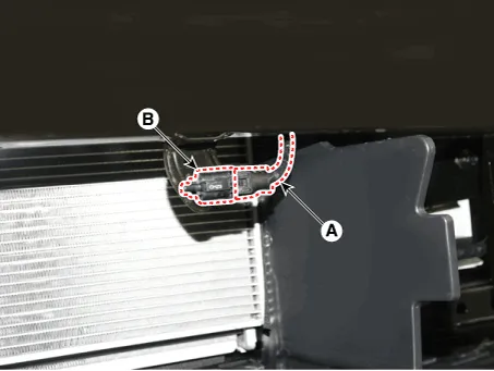
|
| •
| Note that internal damage may occur when the component is dropped. In this case, use it after inspecting. |
|
| 1. | Install in the reverse order of removal. |
Description and operation
DescriptionThe GDI injector is similar to a standard injector, but sprays fuel at a much higher pressure directly into the combustion chamber and has a swirl disc to get the fuel swirling as it exits the nozzle.
Description and operation
DescriptionPurge Control Solenoid Valve (PCSV) is a solenoid valve and is installed on the surge tank and controls the passage between the canister and the intake manifold.
Other information:
Repair procedures
Removal1.Disconnect the negative (-) battery terminal.2.Remove the rear package tray trim.(Refer to Body - "Rear Package Tray Trim")3.Loosen the mounting screws and remove the high mounted stop lamp (A).Installation1.Install the high mounted stop lamp.
Description and operation
DescriptionThe compressor is the power unit of the A/C system.It is located on the side of engine block and driven by a V-belt of the engine.The compressor changes low pressure and low temperature refrigerant gas into high pressure and high temperature refrigerant gas.

