Hyundai Elantra (CN7): Engine Control System / Purge Control Solenoid Valve (PCSV)
Description and operation
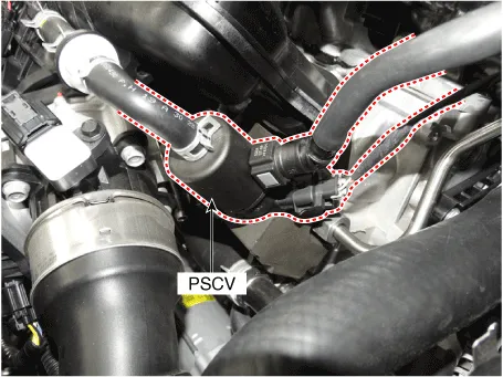
Purge Control Solenoid Valve (PCSV) is a solenoid valve and is installed on the surge tank and controls the passage between the canister and the intake manifold.
The evaporative gases gathered in the canister are delivered to the intake manifold when the PCSV is open by ECM control signal.
Specifications
Item
|
Specification
|
Coil Resistance (Ω)
| 14.21 - 14.79 [23°C (73°F)]
|
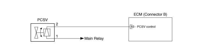
Schematic diagrams
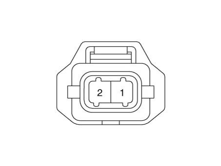
Harness Connector
Repair procedures
| 1. | Turn ignition switch OFF. |
| 2. | Disconnect PCSV connector. |
| 3. | Measure resistance between PCSV terminals 1 and 2. |
| 4. | Check that the resistance is within the specification.
Item
| Specification
| Coil Resistance (Ω)
| 14.21 - 14.79 [23°C (73°F)]
|
|
| 1. | Turn ignition switch OFF and disconnect the battery negative (-) terminal. |
| 2. | Disconnect the purge control solenoid valve connector (A). |
| 3. | Disconnect the vapor hoses (B). |
| 4. | Remove the purge control solenoid valve (C). 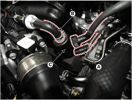
|
| •
| Install the component with the specified torques. |
| •
| Note that internal damage may occur when the component is dropped. In this case, use it after inspecting. |
|
| •
| Be careful of foreign material not to flow into the valve. |
|
| 1. | Install in the reverse order of removal. |
Description and operation
DescriptionAmbient Temperature Sensor (ATS) is installed on the front-end module and senses the ambient temperature. This sensor is exposed to the ambient air temperature in front of the radiator.
Description and operation
DescriptionContinuous Variable Valve Timing (CVVT) system advances or retards the valve timing of the exhaust valve in accordance with the ECM control signal which is calculated by the engine speed and load.
Other information:
Instructions (R-134a)When Handling Refrigerant1.R-134a liquid refrigerant is highly volatile. A drop on the skin of your hand could result in localized frostbite. When handling the refrigerant, be sure to wear gloves. 2.It is standard practice to wear goggles or glasses to protect your eyes, and gloves to protect your hands.
C

