Hyundai Elantra (CN7): AVN System / AVN(Audio Video Navigation) head unit
Components and components location
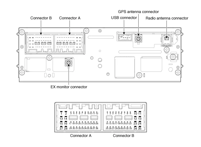
| Components |
|
No
|
Connector A (Int AMP)
|
Connector A (Ext AMP)
|
Connector B
|
| 1 | Rear left speaker (+) | - | - |
| 2 | Reart left speaker (-) | - | MIC Signal (+) |
| 3 | - | AMP Navi Voice (+) | - |
| 4 | - | AMP SPDIF (HI) | - |
| 5 | - | - | Antenna Powr |
| 6 | Camera Power | Camera Power | ILL (+) |
| 7 | Camera Video | Camera Video | MM CAN (HI) |
| 8 | - | - | - |
| 9 | - | - | - |
| 10 | - | - | B+ |
| 11 | - | - | B+ |
| 12 | Steering wheel remote | Steering wheel remote | GND |
| 13 | Front lift speaker (+) | - | GND |
| 14 | Front lift speaker (-) | - | MIC GND |
| 15 | Front right speaker (-) | - | MIC Signal (-) |
| 16 | Front right speaker (+) | - | - |
| 17 | - | AMP Navi Voice (-) | - |
| 18 | - | AMP SPDIF (LOW) | - |
| 19 | - | AMP SPDIF GND | - |
| 20 | Camera Power GND | Camera Power GND | MM CAN (LOW) |
| 21 | Camera Video GND | Camera Video GND | - |
| 22 | - | - | ACC |
| 23 | - | - | - |
| 24 | - | - | - |
| 25 | - | - | - |
| 26 | Steering wheel remote GND | Steering wheel remote GND | - |
| 27 | Rear right speaker (-) | - | - |
| 28 | Rear right speaker (+) | - | - |
| 29 | - | - | - |
| 30 | - | - | - |
| 31 | - | - | - |
| 32 | - | - | - |
| 33 | Camera shield ground | - | IGN 1 |
| 34 | - | - | - |
| 35 | - | - | - |
| 36 | - | - | |
| 37 | - | - | |
| 38 | Speed | Speed |
|
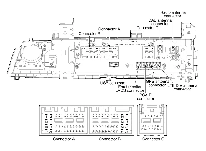
No
|
Connector A (Ext AMP)
|
Connector B
|
Connector C
|
| 1 | - | - | - |
| 2 | - | MIC Signal (+) | I-CAN (HI) |
| 3 | AMP Navi Voice (+) | - | - |
| 4 | AMP SPDIF (HI) | - | - |
| 5 | - | - | - |
| 6 | Camera Power | ILL (+) | - |
| 7 | Camera Video | MM CAN (HI) | - |
| 8 | - | - | - |
| 9 | - | - | I-CAN (LOW) |
| 10 | - | B+ | - |
| 11 | USB Detect | B+ | - |
| 12 | Steering wheel remote | GND | - |
| 13 | - | GND | - |
| 14 | - | - | - |
| 15 | - | MIC Signal (-) | - |
| 16 | - | - | MTS Key |
| 17 | AMP Navi Voice (-) | - | - |
| 18 | AMP SPDIF (LOW) | - | - |
| 19 | AMP SPDIF GND | ILL (-) | - |
| 20 | Camera Power GND | MM CAN (LOW) | - |
| 21 | Camera Video GND | - | - |
| 22 | - | ACC | |
| 23 | - | - | |
| 24 | - | Front monitor power | |
| 25 | - | - | |
| 26 | Steering wheel remote GND | - | |
| 27 | - | - | |
| 28 | - | - | |
| 29 | - | - | |
| 30 | - | - | |
| 31 | - | - | |
| 32 | - | - | |
| 33 | Camera shield ground | IGN 1 | |
| 34 | - | - | |
| 35 | - | Front monitor power ground | |
| 36 | - | ||
| 37 | - | ||
| 38 | Speed |

Repair procedures
| Removal |
|

| 1. | Disconnect the negative (-) battery terminal. |
| 2. | When removing with a flat-tip screwdriver or remover, remove the steering column shroud upper panel (A).
|

| 3. | When removing with a flat-tip screwdriver or remover, remove the floor console side garnish (A).
|

| 4. | When removing with a flat-tip screwdriver or remover, remove the crash pad garnish[CTR] (A).
|

| 5. | Remove the heater & A/C control unit. (Refer to Heating, Ventilation and Air Conditioning - "Heater & A/C Control Unit (DATC)") (Refer to Heating, Ventilation and Air Conditioning - "Heater & A/C Control Unit (Manual)") |
| 6. | Remove the AVN head unit (A) after loosening mounting screws.
|

| 7. | Remove the AVN head unit connectors and cables (A).
|

| Installation |
| 1. | Install the AVN head unit. |
| 2. | Install the heater & A/C control unit. |
| 3. | Install the crash pad garnish[CTR]. |
| 4. | Install the floor console side garnish. |
| 5. | Install the steering column shroud upper panel. |
| 6. | Disconnect the negative (-) battery terminal.
|

Component Location1. AVN head unit2. Crash pad antenna3. Bluelink keyboard & Hands-free mic (Built-in overhead console)4. Steering wheel remote control5.
Components and components location Components NO Connector A NO Connector B 1BATT (+)1Subwoofer 2 (+)2BATT (+)2Subwoofer 1 (+)3BATT (+)3Sub woofer speaker (+)4BATT (+)4-5-5-6Multimedia CAN (High)6-7Multimedia CAN (Low)7Navigation voice (+)8ACC8-9-9-10-10-11-11-12-12Rear door speaker - RH (+)13-13Rear door speaker - LH (+)14-14Center speaker (+)15-15 -16Ground16Front door tweeter speaker - RH (-)17Ground17Front door tweeter speaker - LH (-)18Ground18Sub woofer speaker (-)19Ground19-20SPDIF (High)20-21SPDIF (Low)21Navigation voice (+)22SPDIF GND22-23-23-24IGN 124-25-25Rear door speaker - RH (-)26-26Rear door speaker - LH (-) 27-27Center speaker (+)28-28 - Repair procedures Removal1.
Other information:
Hyundai Elantra (CN7) 2021-2026 Service Manual: License Lamps
Repair procedures Removal1.Disconnect the negative (-) battery terminal.2.Push the lock pin (B) and remove the license lamp (A).3.Disconnect the license lamp connector (A).4.Replace the bulb (A).Installation1.Connect the license lamp connector.2.Install the license lamp.
Hyundai Elantra (CN7) 2021-2026 Service Manual: A/C Pressure Transducer
Description and operation DescriptionThe A/C Pressure Transducer (APT) converts the pressure value of high pressure line into voltage value after measuring it. By converted voltage value, engine ECU controls the cooling fan by operating it high speed or low speed.
Categories
- Manuals Home
- Hyundai Elantra Owners Manual
- Hyundai Elantra Service Manual
- Body (Interior and Exterior)
- Front Radar Unit
- Engine Mechanical System
- New on site
- Most important about car
