Hyundai Elantra (CN7): AVN System / External AMP
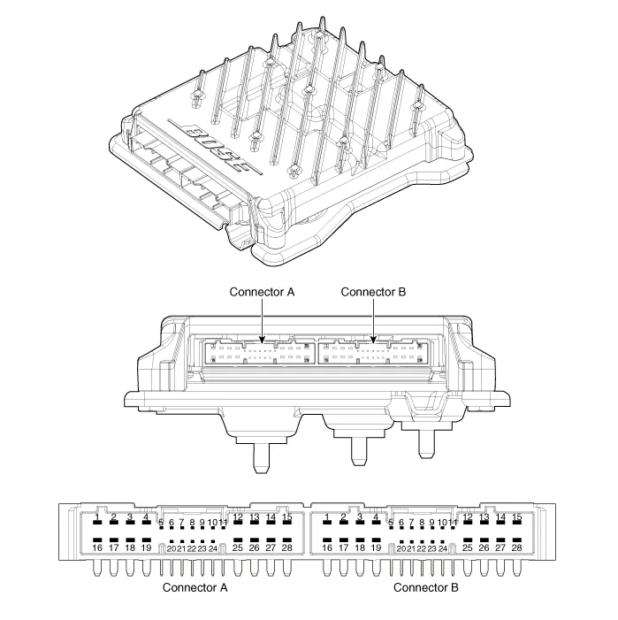
Components and components location
| Components |
|
NO
|
Connector A
|
NO
|
Connector B
|
| 1 | BATT (+) | 1 | Subwoofer 2 (+) |
| 2 | BATT (+) | 2 | Subwoofer 1 (+) |
| 3 | BATT (+) | 3 | Sub woofer speaker (+) |
| 4 | BATT (+) | 4 | - |
| 5 | - | 5 | - |
| 6 | Multimedia CAN (High) | 6 | - |
| 7 | Multimedia CAN (Low) | 7 | Navigation voice (+) |
| 8 | ACC | 8 | - |
| 9 | - | 9 | - |
| 10 | - | 10 | - |
| 11 | - | 11 | - |
| 12 | - | 12 | Rear door speaker - RH (+) |
| 13 | - | 13 | Rear door speaker - LH (+) |
| 14 | - | 14 | Center speaker (+) |
| 15 | - | 15 | - |
| 16 | Ground | 16 | Front door tweeter speaker - RH (-) |
| 17 | Ground | 17 | Front door tweeter speaker - LH (-) |
| 18 | Ground | 18 | Sub woofer speaker (-) |
| 19 | Ground | 19 | - |
| 20 | SPDIF (High) | 20 | - |
| 21 | SPDIF (Low) | 21 | Navigation voice (+) |
| 22 | SPDIF GND | 22 | - |
| 23 | - | 23 | - |
| 24 | IGN 1 | 24 | - |
| 25 | - | 25 | Rear door speaker - RH (-) |
| 26 | - | 26 | Rear door speaker - LH (-) |
| 27 | - | 27 | Center speaker (+) |
| 28 | - | 28 | - |
Repair procedures
| Removal |
| 1. | Disconnect the negative (-) battery terminal. |
| 2. | Open the trunk, remove the right luggage side trim. (Refer to Body - "Luggage Side Trim") |
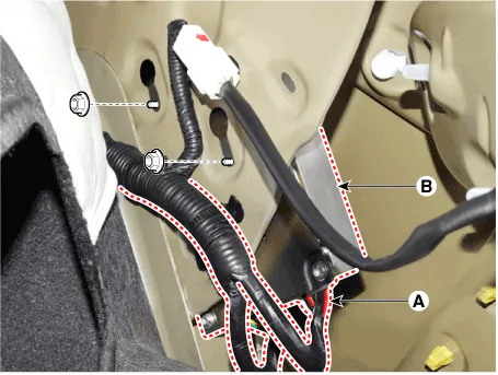
| 3. | Remove the external amplifier (B) after disconneting the connector (A) and loosening the mounting nuts.
|
| Installation |
| 1. | Install the external amplifier after connecting the connector. |
| 2. | Install the right luggage side trim. |
| 3. | Connect the negative (-) battery terminal.
|

Components and components location ComponentsMiddle EastConnector Pin Information No Connector A (Int AMP) Connector A (Ext AMP) Connector B 1Rear left speaker (+)--2Reart left speaker (-)-MIC Signal (+)3-AMP Navi Voice (+)-4-AMP SPDIF (HI)-5--Antenna Powr6Camera PowerCamera PowerILL (+)7Camera VideoCamera VideoMM CAN (HI)8---9---10--B+11--B+12Steering wheel remote Steering wheel remote GND13Front lift speaker (+)-GND14Front lift speaker (-)-MIC GND15Front right speaker (-)-MIC Signal (-)16Front right speaker (+)--17-AMP Navi Voice (-)-18-AMP SPDIF (LOW)-19-AMP SPDIF GND-20Camera Power GNDCamera Power GNDMM CAN (LOW)21Camera Video GNDCamera Video GND-22--ACC23---24---25---26Steering wheel remote GNDSteering wheel remote GND-27Rear right speaker (-)--28Rear right speaker (+)--29---30---31---32---33Camera shield ground-IGN 134---35---36--37--38SpeedSpeedGeneralConnector Pin Information No Connector A (Ext AMP) Connector B Connector C 1---2-MIC Signal (+)I-CAN (HI)3AMP Navi Voice (+)--4AMP SPDIF (HI)--5---6Camera PowerILL (+)-7Camera VideoMM CAN (HI)-8---9--I-CAN (LOW)10-B+-11USB DetectB+-12Steering wheel remote GND-13-GND-14---15-MIC Signal (-)-16--MTS Key17AMP Navi Voice (-)--18AMP SPDIF (LOW)--19AMP SPDIF GNDILL (-)-20Camera Power GNDMM CAN (LOW)-21Camera Video GND--22-ACC23--24-Front monitor power25--26Steering wheel remote GND-27--28--29--30--31--32--33Camera shield groundIGN 134--35-Front monitor power ground36-37-38Speed Repair procedures Removal • Take care not to scratch the cluster fascia panel and related parts.
Components and components location Components1. Left Remote Control Switch (Audio + Bluetooth)2. Right Remote Control Switch (Cruise + Trip) Schematic diagrams Circuit Diagram[Without paddle shift][With paddle shift][Audio + B/Tooth][Audio + B/Tooth + Voice][Trip][Trip / Cruise][Trip + Cruise + LFA)[Trip + Cruise + LFA + MSLA)[Trip + Smart Cruise + LFA)[Trip + Smart Cruise + LFA + MSLA) Repair procedures Inspection1.
Other information:
Hyundai Elantra (CN7) 2021-2026 Service Manual: A/C Pressure Transducer
Description and operation DescriptionThe A/C Pressure Transducer (APT) converts the pressure value of high pressure line into voltage value after measuring it. By converted voltage value, engine ECU controls the cooling fan by operating it high speed or low speed.
Hyundai Elantra (CN7) 2021-2026 Service Manual: Heater Core
Repair procedures Replacement1.Disconnect the negative (-) battery terminal. 2.Remove the heater and blower assembly.(Refer to Heater - "Heater Unit") 3.Remove the heater core cover (A) after loosening the mounting screws.4.Pull out the heater core (A) from the heater unit.
Categories
- Manuals Home
- Hyundai Elantra Owners Manual
- Hyundai Elantra Service Manual
- Engine Control / Fuel System
- Auto Hold. Warning messages
- Drive Mode
- New on site
- Most important about car
