Hyundai Elantra (CN7): Crash Pad / Cluster Fascia Side Panel
Hyundai Elantra (CN7) 2021-2026 Service Manual / Body (Interior and Exterior) / Crash Pad / Cluster Fascia Side Panel
Repair procedures
| Replacement |
|

|

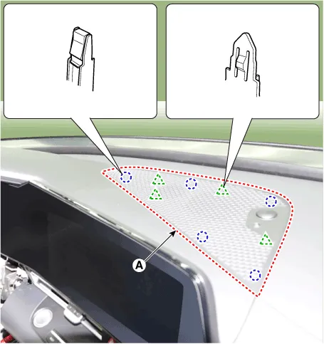
| 1. | Using a screwdriver or remover, remove the photo sensor cover (A).
|
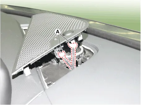
| 2. | Press the lock pin, separate the connectors (A).
|
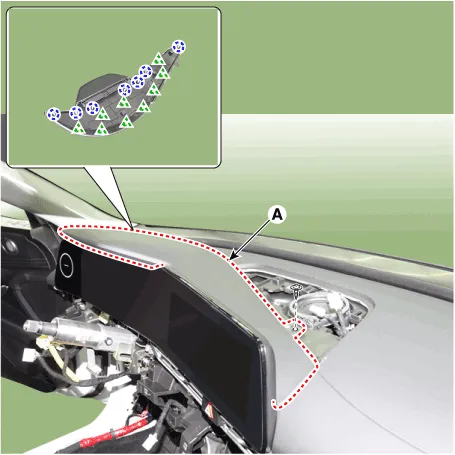
| 3. | Using a screwdriver or remover, remove the cluster fascia panel upper garnish (A).
|
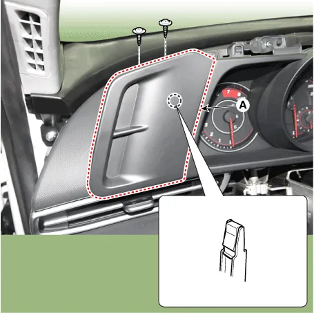
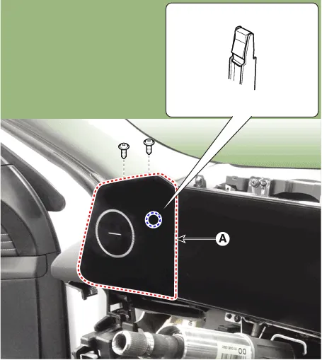
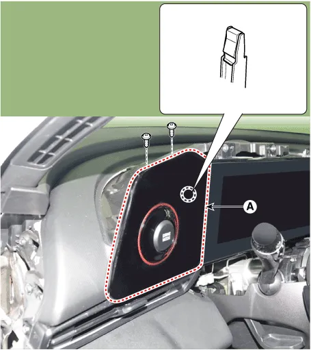
| 4. | Loosen the mounting screw, remove the cluster fascia side panel (A). [4.2" TFT LCD]
[10.25" TFT cluster]
[N Line]
|
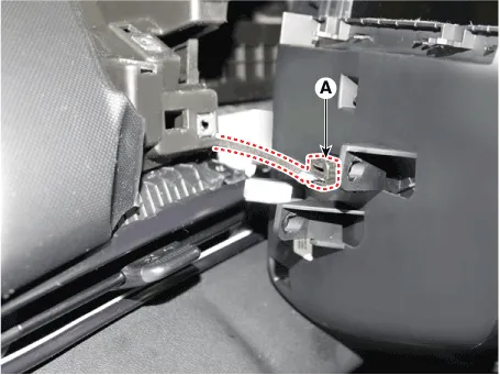
| 5. | Press the lock pin, separate the cluster fascia side panel connector (A). [N Line]
|
| 6. | To install, reverse the removal procedure.
|

Components[This illustration shows the LHD type. RHD type is symmetrical.]1. Crash pad assembly2. Crash pad lower panel3. Crash pad side cover [LH]4. Crash pad side cover [RH]
Components and components location Components Location[This illustration shows the LHD type. RHD type is symmetrical.]1. Center fascia panel Repair procedures Replacement • When removing with a flat - tip screwdriver or remover, wrap protective tape around the tools to prevent damage to components.
Categories
- Manuals Home
- Hyundai Elantra Owners Manual
- Hyundai Elantra Service Manual
- Auto Hold. Warning messages
- Engine Control / Fuel System
- Brake System
- New on site
- Most important about car

Copyright © 2026 www.helantra7.com - 0.0144