
Hyundai Elantra (CN7): Crash Pad / Cluster Fascia Panel
Components and components location
| Components Location |
| [This illustration shows the LHD type. RHD type is symmetrical.] |
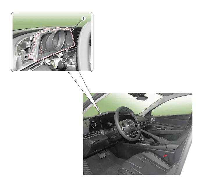
| 1. Center fascia panel |
Repair procedures
| Replacement |
|

|

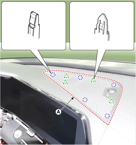
| 1. | Using a screwdriver or remover, remove the photo sensor cover (A).
|
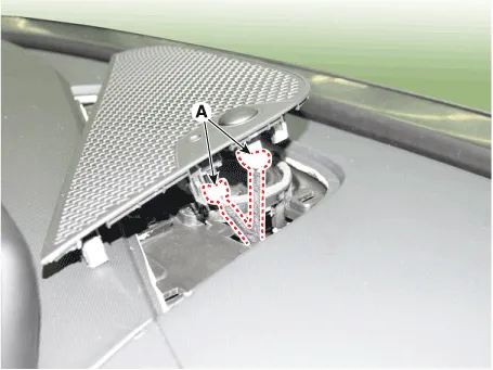
| 2. | Press the lock pin, separate the connectors (A).
|
| 3. | Using a screwdriver or remover, remove the cluster fascia panel upper garnish (A).
|
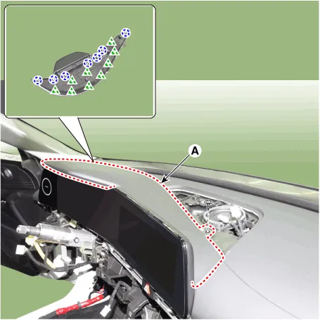
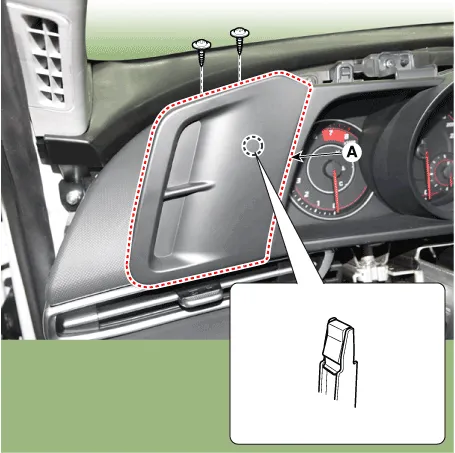
| 4. | Loosen the mounting screws and remove the center fascia side panel (A).
|
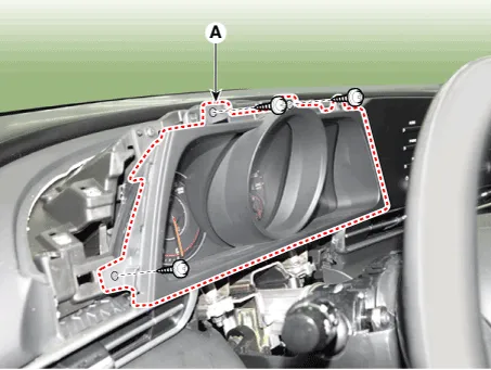
| 5. | Loosen the mounting screws and remove the center fascia panel (A).
|
| 6. | To install, reverse the removal procedure.
|

Repair procedures Replacement • When removing with a flat - tip screwdriver or remover, wrap protective tape around the tools to prevent damage to components.
Components and components location Components Location[This illustration shows the LHD type. RHD type is symmetrical.]1. Crash pad garnish [LH]3. Crash pad garnish [CTR]2.
Other information:
Hyundai Elantra (CN7) 2021-2026 Service Manual: Repair procedures
Refrigerant System Service Basics (R-134a)Refrigerant Recovery Use only service equipment that is U.L-listed and is certified to meet the requirements of SAE J2210 to remove HFC-134a(R-134a) from the air conditioning system. • Air conditioning refrigerant or lubricant vapor can irritate your eyes, nose, or
Hyundai Elantra (CN7) 2021-2026 Service Manual: Condenser
Components and components location Components Location[General type]1. Condenser[N Line]1. Condenser Repair procedures Inspection1.Check the condenser fins for clogging and damage. If clogged, clean them with water, and blow them with compressed air.
Categories
- Manuals Home
- Hyundai Elantra Owners Manual
- Hyundai Elantra Service Manual
- Drive Mode
- Troubleshooting
- Integrated Thermal Management Module (ITM)
- New on site
- Most important about car
