Hyundai Elantra (CN7): Interior Trim / Cowl Side Trim
Components and components location
| Component Location |
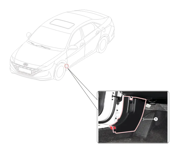
| 1. Cowl side trim |
Repair procedures
| Replacement |
|

|

| 1. | Remove the front door scuff trim. (Refer to Interior Trim - "Door Scuff Trim") |
| 2. | Remove the hood latch release handle. (Refer to Hood - "Hood Latch Release Handle") |
| 3. | Remove the front door body side weatherstrip. (Refer to Front Door - "Front Door Side Weatherstrip") |
| 4. | Using a screwdriver or remover, remove the cowl side trim (A).
|
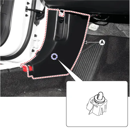
| 5. | To install, reverse the removal procedure.
|

Components and components location Component Location 1. Front door scuff trim2. Rear door scuff trim Repair procedures Replacement[Front door scuff trim] • When removing with a flat - tip screwdriver or remover, wrap protective tape around the tools to prevent damage to components.
Components and components location Component Location 1. Front pillar trim Repair procedures Replacement • When removing with a flat - tip screwdriver or remover, wrap protective tape around the tools to prevent damage to components.
Other information:
Hyundai Elantra (CN7) 2021-2026 Service Manual: In-car Sensor
Description and operation DescriptionThe In-car air temperature sensor is built in the heater & A/C control unit.The sensor contains a thermistor which measures the temperature of the inside. The signal decided by the resistance value which changes in accordance with perceived inside temperature, is delivered to heater control unit and accor
Hyundai Elantra (CN7) 2021-2026 Service Manual: Parking Distance Warning (PDW)
Description and operation Description• PDW consists of 8 sensors (front : 4 units, rear : 4 units) that are used to detect obstacles and transmit the result in three separate warning levels, the first, second and third to IBU via LIN communication.
Categories
- Manuals Home
- Hyundai Elantra Owners Manual
- Hyundai Elantra Service Manual
- Specifications
- Instrument Panel Overview
- Maintenance
- New on site
- Most important about car
