
Hyundai Elantra (CN7): Interior Trim / Door Scuff Trim
Components and components location
| Component Location |
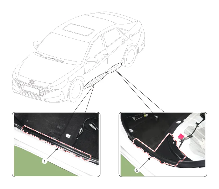
| 1. Front door scuff trim | 2. Rear door scuff trim |
Repair procedures
| Replacement |
|

|

| 1. | Remove the front door body side weatherstrip. (Refer to Front Door - "Front Door Side Weatherstrip") |
| 2. | Using a screwdriver or remover, remove the front door scuff trim (A).
|
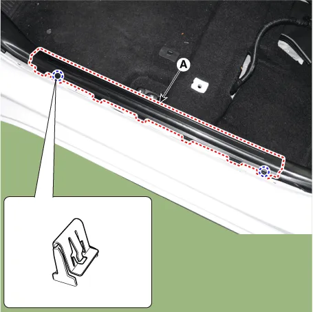
| 3. | To install, reverse the removal procedure.
|

|
|
| 1. | Remove the rear door body side weatherstrip. (Refer to Rear Door - "Rear Door Side Weatherstrip") |
| 2. | Remove the rear seat cushion assembly. (Refer to Rear Seat - "Rear Seat Assembly") |
| 3. | Loosen the mounting screws and remove the rear door scuff trim (A).
|
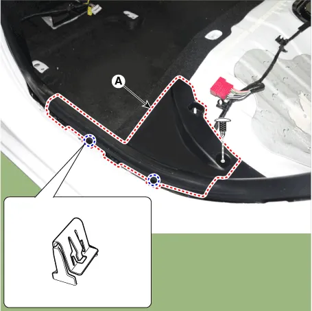
| 4. | To install, reverse the removal procedure.
|
Components1. Cowl side trim 2. Front door scuff trim 3. Rear door scuff trim 4. Front pillar trim 5. Center pillar upper trim 6. Center pillar lower trim 7.
Components and components location Component Location 1. Cowl side trim Repair procedures Replacement • When removing with a flat-tip screwdriver or remover, wrap protective tape around the tools to prevent damage to components.
Other information:
Hyundai Elantra (CN7) 2021-2026 Service Manual: Intake Actuator
Description and operation DescriptionThe intake actuator is located at the blower unit. It regulates the intake door by a signal from the control unit. Pressing the intake selection switch will shift between recirculation and fresh air modes. Components and components location Components Location1.
Hyundai Elantra (CN7) 2021-2026 Service Manual: Front View Camera Unit
Schematic diagrams Circuit Diagram Repair procedures Removal1.Disconnect the negative (-) battery terminal.2.Remove the cover (A) & (B).3.Disconnect the front view camera unit connector (A).4.Separate the fixed points (A) of coupler.5.
Categories
- Manuals Home
- Hyundai Elantra Owners Manual
- Hyundai Elantra Service Manual
- Rear Seats
- Specifications
- Driver assistance system
- New on site
- Most important about car
