Hyundai Elantra (CN7): Cylinder Head Assembly / Cylinder Head Cover
Hyundai Elantra (CN7) 2021-2026 Service Manual / Engine Mechanical System / Cylinder Head Assembly / Cylinder Head Cover
Components and components location
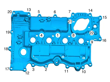
| Components |
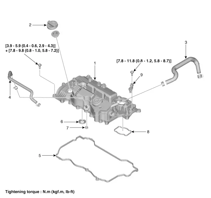
| 1. Cylinder head cover 2. Engine oil filler cap 3. Breather hose 4. PCV hose 5. Cylinder head cover gasket | 6. Oil seal 7. Gasket 8. High pressure fuel pump gasket 9. Cam position sensor |
Repair procedures
| Removal |
| 1. | Disconnect the battery negative terminal. |
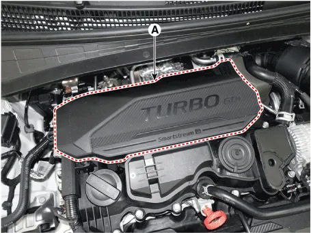
| 2. | Remove the engine cover (A).
|
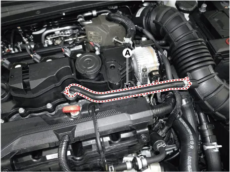
| 3. | Disconnect the breather hoses (A).
|

| 4. | Disconnect the wiring connectors and harness clamps and remove the connector brackets around the cylinder head cover.
|
| 5. | Remove the high pressure fuel pump. (Refer to Engine Control / Fuel System - "High Pressure Fuel Pump") |
| 6. | Remove the ignition coil. (Refer to Engine Electrical System - "Ignition Coil") |
| 7. | Remove the CVVD actuator. (Refer to Engine Control / Fuel System - "CVVD Acuator") |
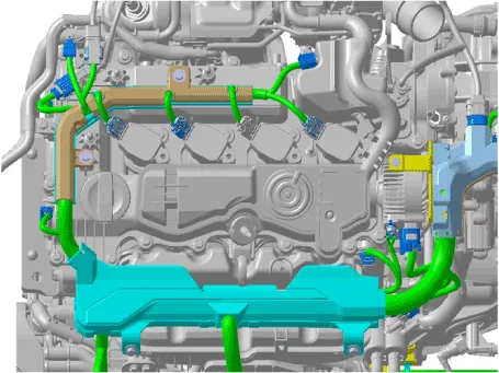
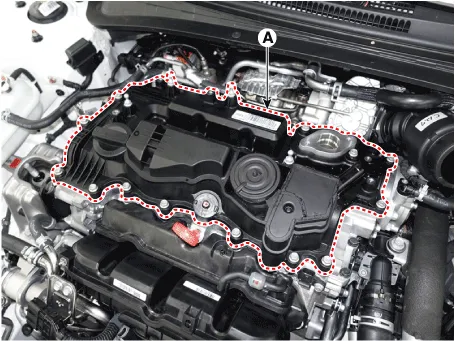
| 8. | Remove the cylinder head cover (A) with gasket.
|
| Installation |
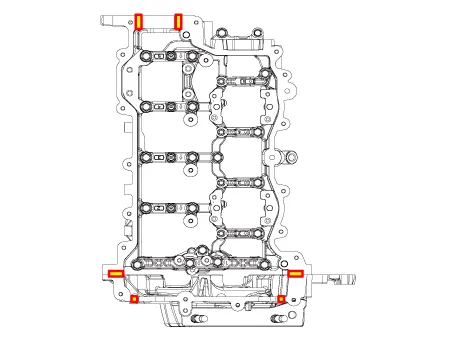
| 1. | Install the cylinder head cover.
|

| 2. | Install the other parts in the reverse order of removal. |
Repair procedures Removal 1.Disconnect the battery negative terminal.2.Remove the cylinder head cover. (Refer to Cylinder Head Assembly - "Cylinder Head Cover")3.
Other information:
Hyundai Elantra (CN7) 2021-2026 Service Manual: Repair procedures
Inspection1.Check for resistance between terminals in each switch position (LH).[LH : Audio + Hands free] Switch Resistance (±5%) SEEK Up430 ΩSEEK Down1.11 kΩMODE2.11 kΩMUTE3.11 kΩVolume (+)4.
Hyundai Elantra (CN7) 2021-2026 Service Manual: ADAS Parking ECU (ADAS_PRK)
Components and components location Components and Components Location Repair procedures Removal • Use a plastic panel removal tool to remove interior trim pieces without marring the surface.• Take care not to bend or scratch the trim and panels.
Categories
- Manuals Home
- Hyundai Elantra Owners Manual
- Hyundai Elantra Service Manual
- Engine Control / Fuel System
- Body Electrical System
- Engine Mechanical System
- New on site
- Most important about car

Copyright © 2026 www.helantra7.com - 0.0106