Hyundai Elantra (CN7): Intake And Exhaust System / Exhaust Manifold
Components and components location
| Components |
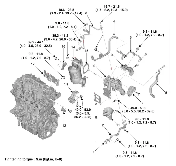
| 1. Oil drain pipe gasket 2. Oil drain pipe 3. Oil feed pipe 4. Torbo charhe water outlet hose & pipe B 5. Torbo charhe water inlet pipe 6. Torbo charhe water outlet pipe A 7. Electric waste gate actuator (EWGA) 8. Exhaust manifold gasket 9. Exhaust manifold & Turbo charger | 10. Exhaust manifold heat protector A 11. Exhaust manifold heat protector B 12. Intercooler pipe braket 13. Exhaust manifold & Turbo charger stay bracket 14. Warm up catalytic converter 15. Warm up catalytic converter gasket 16. Warm up catalytic converter upper stay bracket 17. Cylinder head heat peotector |
Repair procedures
| Removal and Installation |
| 1. | Disconnect the negative battery terminal. |
| 2. | Remove the engine cover. (Refer to Engine and Transaxle Assembly - "Engine Cover") |
| 3. | Remove the engine room under cover. (Refer to Engine and Transaxle Assembly - "Engine Room Under Cover") |
| 4. | Drain the coolant. (Refer to Cooling System - "Coolant") |
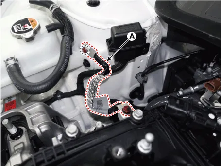
| 5. | Disconnect the engine ground cable (A).
|
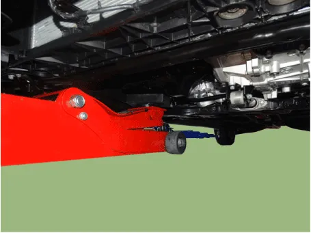
| 6. | Install the jack to the edge of oil pan.
|

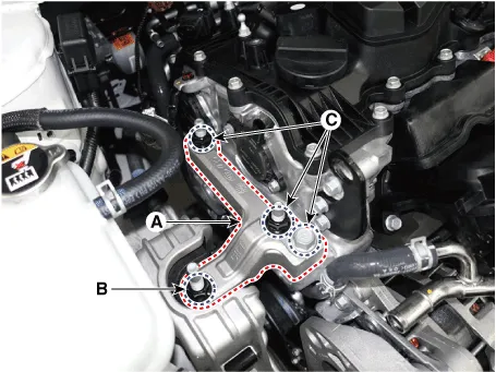
| 7. | Remove the engine mounting support bracket (A).
|
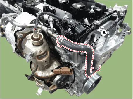
| 8. | Disconnect the turbo charger outlet hose (A).
|
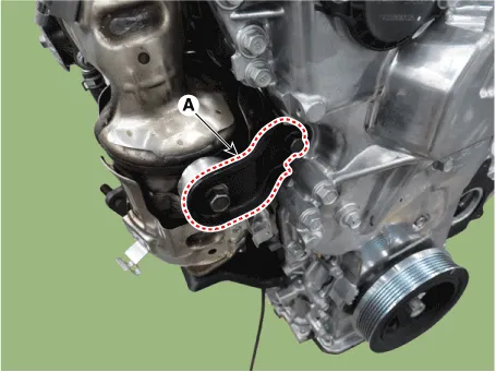
| 9. | Remove the warm up catalytic converter(WCC) upper stay bracket (A).
|
| 10. | Remove the front muffler. (Refer to Intake and Exhaust Manifold - "Front Muffler") |
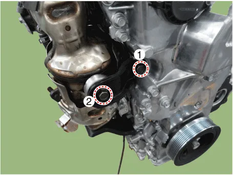
| 11. | Remove the warm up catalytic converter(WCC) lower stay bracket (A).
|
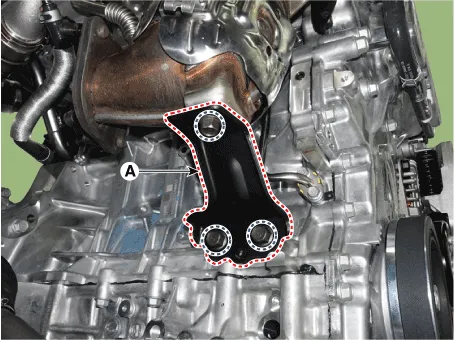
| 12. | Remove the warm up catalytic converter (WCC) (A).
|
| 13. | Remove the air duct and air cleaner assembly. (Refer to Intake and Exhaust System - "Air Cleaner") |
| 14. | Remove the battery and battery tray. (Refer to Engine Electrical System - "Battery") |
| 15. | Disconnect the turbo charger intake hoseB (A).
|
| 16. | Remove the tbreather hose and pipe (A).
|
| 17. | Remove the turbo charger inlet pipe (A).
|
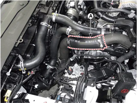
| 18. | Disconnect the intercooler inlet hose (A).
|
| 19. | Remove the intercooler hose & pipe (A).
|
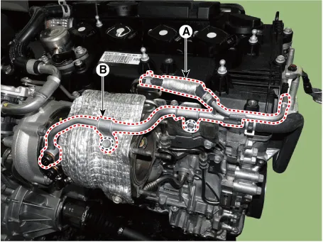
| 20. | Disconnect the turbo charger outlet hose (A), and then remove the water pipe (B).
|
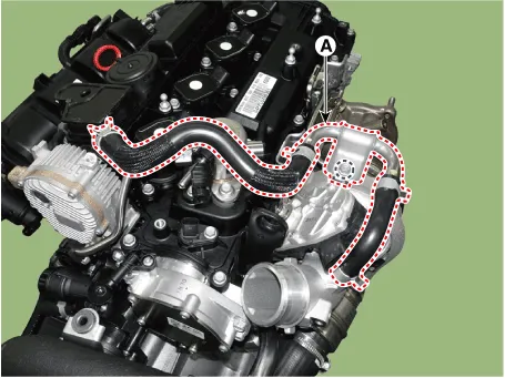
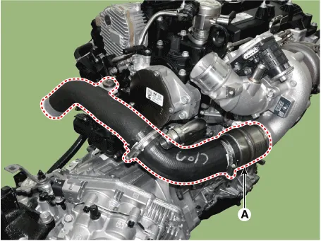
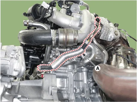
| 21. | Remove the turbo charger inlet hose & pipe (A).
|
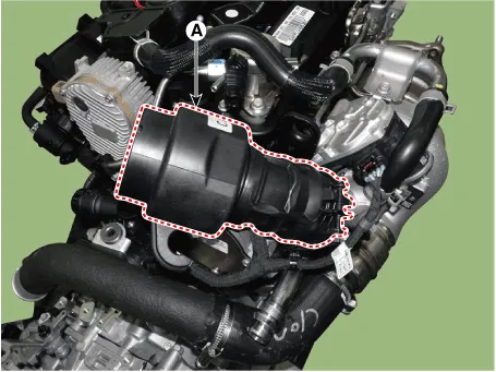
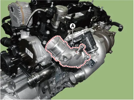
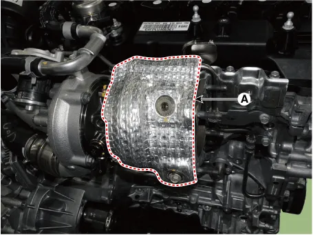
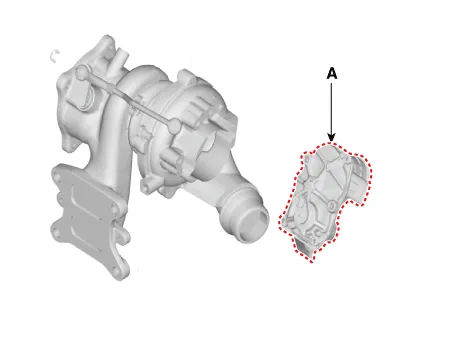
| 22. | Remove the turbo charger heat protect (A).
|
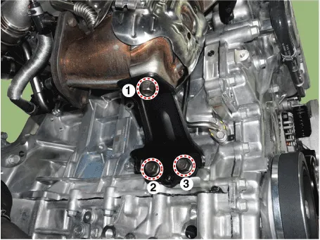
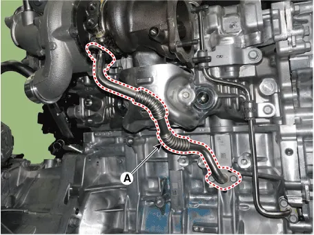
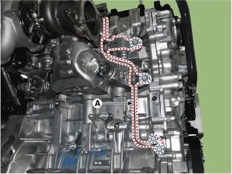
| 23. | Remove the turbo charger oil drain pipe(A).
|
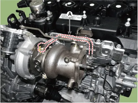
| 24. | Remove the turbo charger oil feed pipe(A).
|
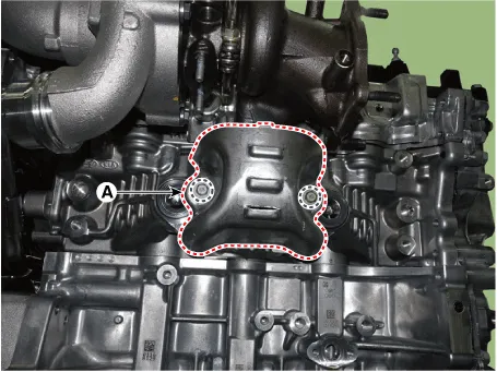
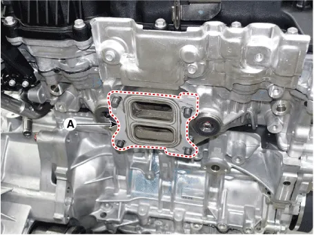
| 25. | Remove the turbo charger heat protector (A).
|
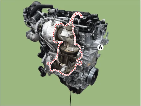
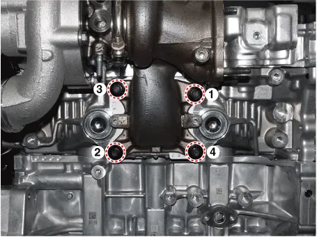
| 26. | Remove the exhaust manifold & turbo charger (A).
|
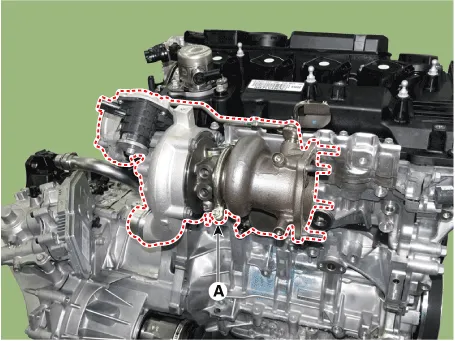
| 27. | Remove the exhaust manifold & turbo charger gasket (A).
|
| 28. | Remove the C- ring, and then remove the electric WGT control actuator (A) after loosening the mounting bolts.
|
| 29. | Install in the reverse order of removal.
|
Components and components location Components1. Electronic throttle body (ETC)2. Return hose3. Return pipe4. Intake manifold5. Intake manifold gasket Repair procedures Removal and Installation1.
Repair procedures Removal and Installation1.Remove the Turbocharger & Exhaust Manifold.(Intake And Exhaust System - "Exhaust Manifold")On-vehicle InspectionTurbocharger Diagnostic Flow If any problem related with turbocharger, such as lack of engine power, poor acceleration, abnormal engine noise or oil leaks, may occur, check the turbocharger according to the procedure as follows.
Other information:
Hyundai Elantra (CN7) 2021-2026 Service Manual: Head Lamp Leveling Device
Components and components location Component Location1. Head lamp leveling actuator2. Head lamp leveling switch Head Lamp Leveling Switch Schematic diagrams Schematic Diagrams Repair procedures Replacement1.Disconnect the negative (-) battery terminal.
Hyundai Elantra (CN7) 2021-2026 Service Manual: Front Radar Unit
Components and components location Components Location1. Front rader unit Specifications Specification Item Specification Power supply (V)12Operation voltage (V)9 - 16 Schematic diagrams Circuit DiagramTerminal function Pin No Te
Categories
- Manuals Home
- Hyundai Elantra Owners Manual
- Hyundai Elantra Service Manual
- Engine Control / Fuel System
- General Tightening Torque Table. General information
- Drive Mode
- New on site
- Most important about car
