Hyundai Elantra (CN7): Intake And Exhaust System / Intake Manifold
Components and components location
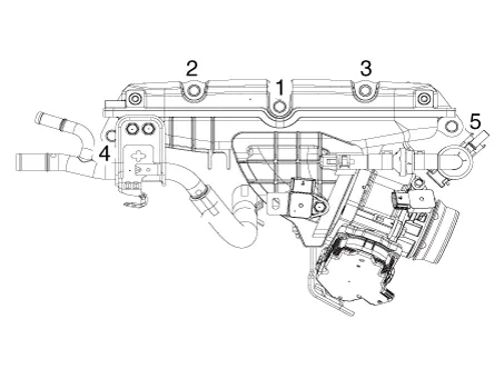
| Components |
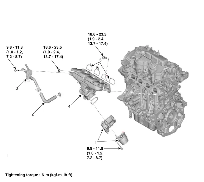
| 1. Electronic throttle body (ETC) 2. Return hose 3. Return pipe | 4. Intake manifold 5. Intake manifold gasket |
Repair procedures
| Removal and Installation |
| 1. | Disconnect the battery negative terminal. |
| 2. | Remove the engine cover. (Refer to Engine and Transaxle Assembly - "Engine Cover") |
| 3. | Remove the engine wire harness connectors and wire harness clamps from cylinder head and the intake manifold.
|
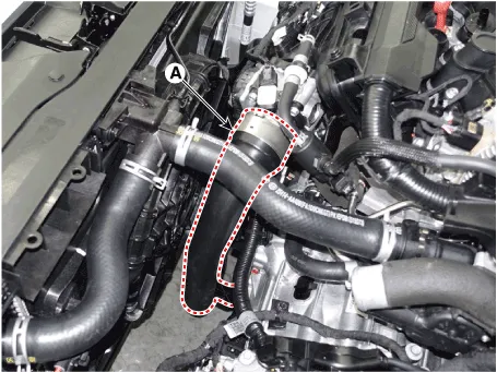
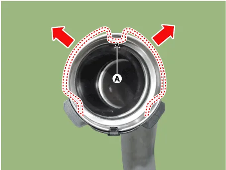
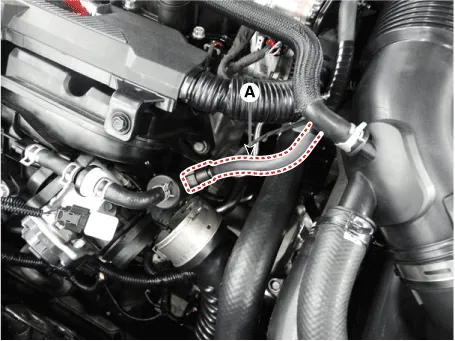
| 4. | Disconnect the intercooler outlet hose (A).
|

| 5. | Remove the purge control solenoid valve (PCSV) hose (A).
|
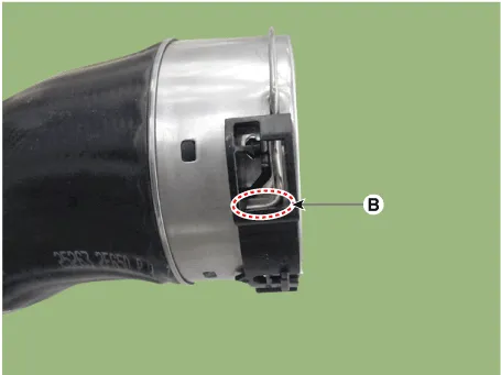
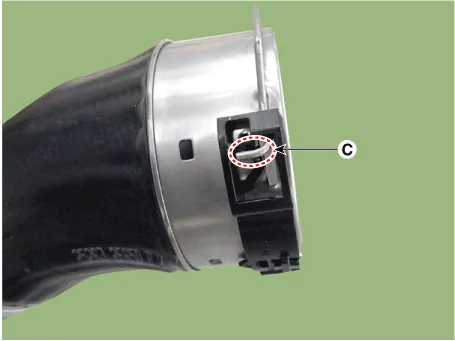
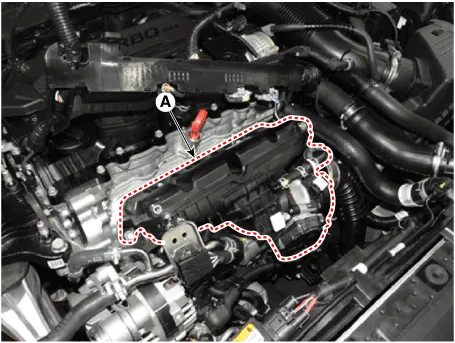
| 6. | Remove the water return hose & pipe bracket bolts (A).
|
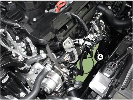
| 7. | Remove the Intake Manifold (A).
|

| 8. | Install in the reverse order of removal. |
Components and components location Components1. Air cleaner cover2. Air cleaner element3. Air cleaner body & air duct5. Air intake hose Repair procedures Removal and InstallationAir Cleaner Assembly.
Components and components location Components1. Oil drain pipe gasket2. Oil drain pipe3. Oil feed pipe4. Torbo charhe water outlet hose & pipe B5.
Other information:
Hyundai Elantra (CN7) 2021-2026 Service Manual: Evaporator Core
Repair procedures Replacement1.Disconnect the negative (-) battery terminal. 2.Remove the heater and blower assembly.(Refer to Heater - "Heater Unit") 3.Remove the heater core cover (A) after loosening the mounting screws.4.Pull out the evaporator core (A) from the heater unit.
Hyundai Elantra (CN7) 2021-2026 Service Manual: Parking Distance Warning (PDW)
Description and operation Description• PDW consists of 8 sensors (front : 4 units, rear : 4 units) that are used to detect obstacles and transmit the result in three separate warning levels, the first, second and third to IBU via LIN communication.
Categories
- Manuals Home
- Hyundai Elantra Owners Manual
- Hyundai Elantra Service Manual
- Instrument Panel Overview
- Integrated Thermal Management Module (ITM)
- Brake System
- New on site
- Most important about car
