Hyundai Elantra (CN7): Floor Console / Floor Console Assembly
Components and components location
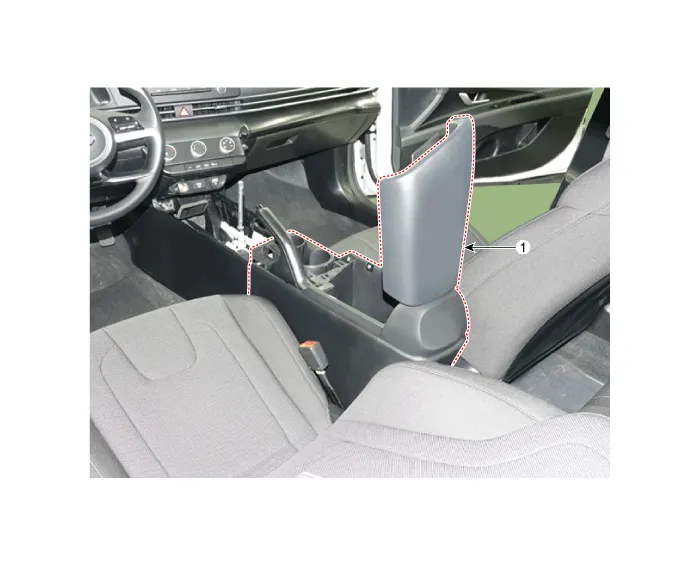
| Component Location |
| [This illustration shows the LHD type. RHD type is symmetrical.] |
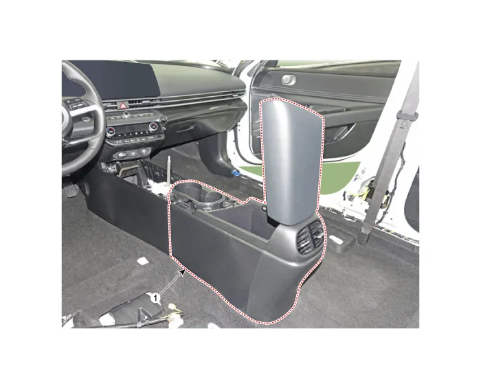
| 1. Floor console assembly |
| 1. Floor console assembly |
Repair procedures
| Replacement |
| [Floor console assembly] |
|

|

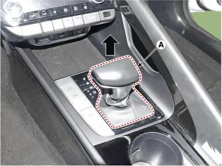
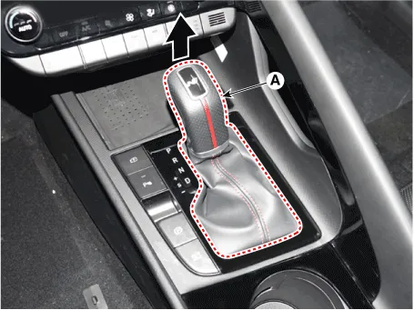
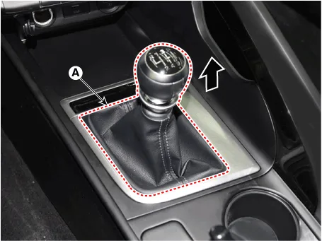
| 1. | To remove the gear knob & gear boots (A) pull both of it up. [General type]
[N Line]
|
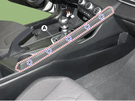
| 2. | Using a screwdriver or remover, remove the floor console side garnish (A).
|
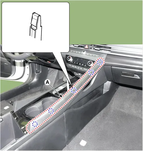
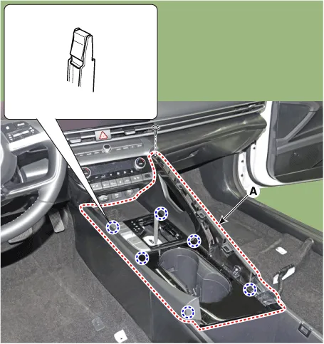
| 3. | After loosening the mounting screw and then using a screwdriver or remover, remove the console upper cover (A).
|
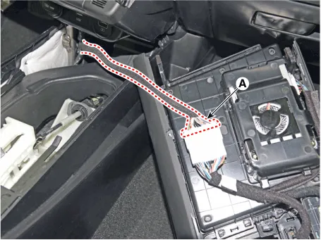
| 4. | Press the lock pin separate the console upper cover connector (A).
|
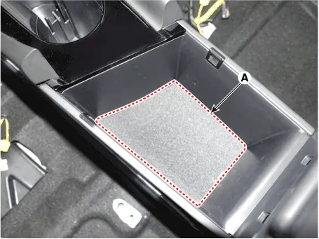
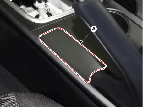
| 5. | Remove the storage box pad (A).
|
| 6. | After loosening the mounting screws and bolts, remove the floor console assembly (A).
|
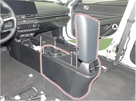
| 7. | To install, reverse the removal procedure.
|

| [Floor console side cover] |
|
|
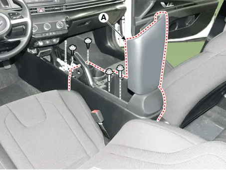
| 1. | Remove the floor console assembly. (Refer to Floor console - "Floor Console Assembly") |
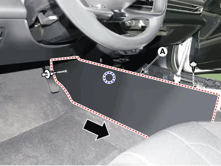
| 2. | After loosening the mounting clip (A) and screw, remove the floor console side cover (B). [LH]
[RH]
|
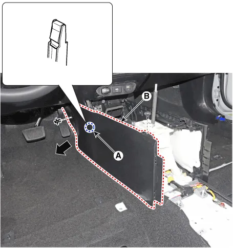
| 3. | To install, reverse the removal procedure.
|
| [Floor console assembly] |
|
|
| 1. | Remove the gear knob & boots (A) pull both of it up.
|
| 2. | Using a screwdriver or remover, remove the floor console side garnish (A).
|
| 3. | Using a screwdriver or remover, remove the parking brake cover (A).
|
| 4. | After loosening the mounting screw and then using a screwdriver or remover, remove the console upper cover (A).
|
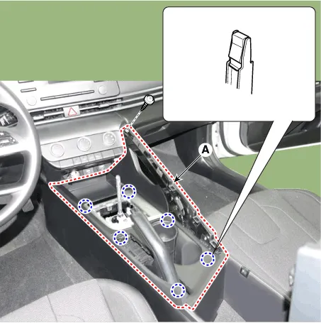
| 5. | Remove the storage box pad (A).
|
| 6. | After loosening the mounting screws and bolts, remove the floor console assembly (A).
|
| 7. | To install, reverse the removal procedure.
|
| [Floor console side cover] |
|
|
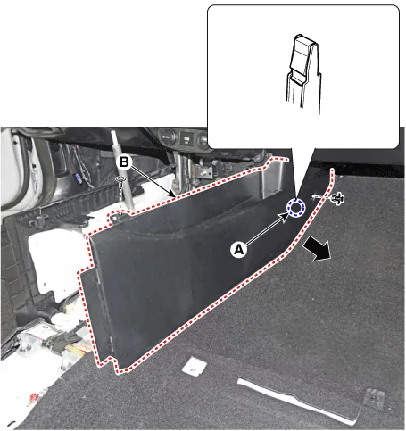
| 1. | Remove the floor console assembly. (Refer to Floor console - "Floor Console Assembly") |
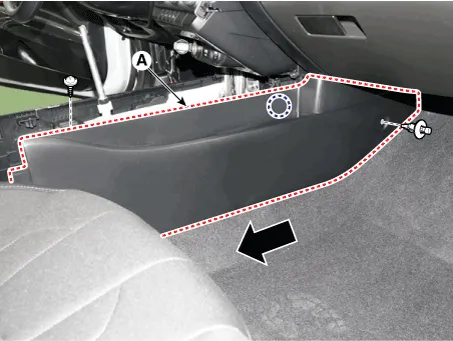
| 2. | After loosening the mounting clip and screw, remove the floor console side cover (A). [LH]
[RH]
|
| 3. | To install, reverse the removal procedure.
|
Components[This illustration shows the LHD type. RHD type is symmetrical.]1. Floor console side cover [LH]2. Floor console side cover [RH]3. Floor console upper cover4.
Components and components location Component Location [This illustration shows the LHD type. RHD type is symmetrical.]1. Rear console cover Repair procedures Replacement • When removing with a flat - tip screwdriver or remover, wrap protective tape around the tools to prevent damage to components.
Other information:
Hyundai Elantra (CN7) 2021-2026 Service Manual: Turn Signal Lamp
Repair procedures Removal1.Disconnect the negative (-) battery terminal.2.Remove the front bumper.(Refer to Body - "Front Bumper Cover")3.Remove the head lamp.4.Remove the bulb socket (A) and turn signal lamp bulb (B) from the lamp assembly.Replacement1.
Hyundai Elantra (CN7) 2021-2026 Service Manual: Ignition Switch Assembly. Repair procedures
Repair procedures Replacement1.Disconnect the negative (-) battery terminal.2.Remove the crash pad lower panel.(Refer to Body - "Crash Pad")3.Remove the steering column upper & Lower shroud.4.Remove the ignition switch and disconnecting the Key Warning / immobilizer connector.
Categories
- Manuals Home
- Hyundai Elantra Owners Manual
- Hyundai Elantra Service Manual
- Vehicle Information
- Body Electrical System
- Instrument Panel Overview
- New on site
- Most important about car
