
Hyundai Elantra (CN7): Dual Clutch Transmission Control System / Input Speed Sensor
Description and operation
| Description |
| • |
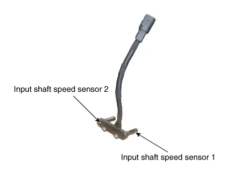
Components location : DCT (Dual Clutch Transmission)
|
| • |
Function
The input shaft speed sensor is important in that it detects the input shaft RPM and sends this information to the Transmission Control Module (TCM). It provides important input information for electric control. The information is needed in all operations, including feedback control, gear shift control and failure detection of other sensors. |
Specifications
| Specification |
|
Item
|
Specification
|
| Type | Hall effect sensor |
| Output signal | High: 11.8 - 16.8 mA |
| Low: 5.9 - 8.4 mA |
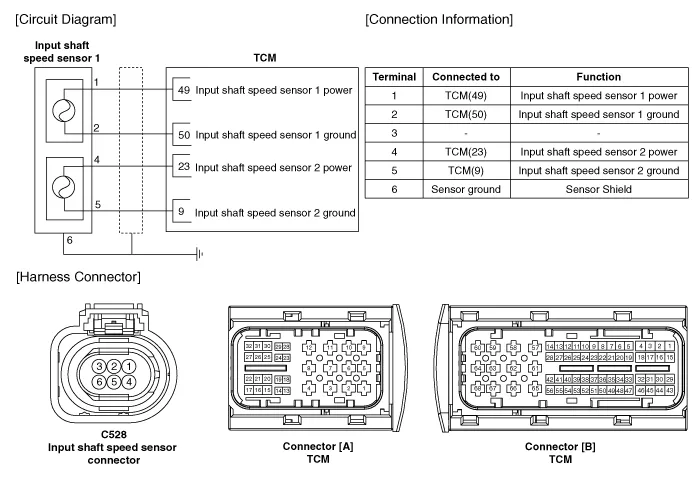
Schematic diagrams
| Circuit Diagram |
Components and components location
| Components |
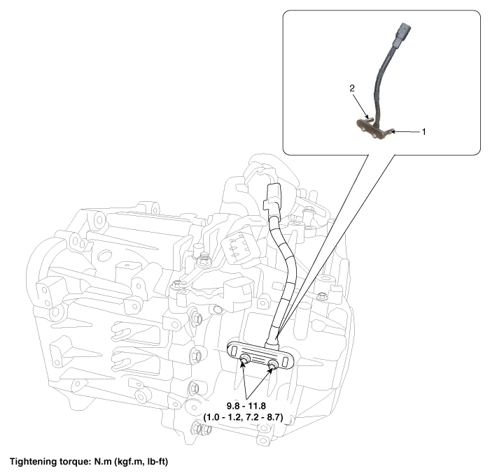
| 1. Input shaft speed sensor 1 (Odd) | 2. Input shaft speed sensor 2 (Even) |
Repair procedures
| Inspection |
| 1. | The DCT system can be more quickly diagnosed for troubles by using the vehicle diagnostic system (diagnostic tool). (Refer to DTC guide) diagnostic tool provides the following information.
|
| Removal |
| 1. | Turn ignition switch OFF and disconnect the battery negative (-) terminal. |
| 2. | Remove the air cleaner assembly and air duct. (Refer to Engine Mechnical System - "Air cleaner") |
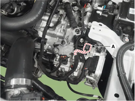
| 3. | Disconnect the input shaft speed sensor connector (A).
|
| 4. | Remove the clutch actuator. (Refer to Dual Clutch Transmission Control System - "Clutch Actuator & TCM Assembly") |
| 5. | Remove the input shaft speed sensor (A).
|
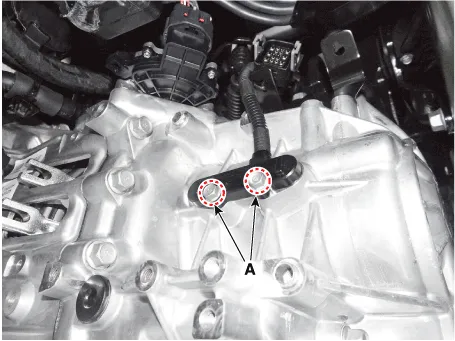
| Installation |
| 1. | Install in the reverse order of removal.
|

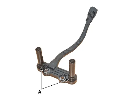
Description and operation Description• Gear actuator uses signals from TCM to control the gear. Specifications Specification Item Specification Operation condition-40 to 257 °F (- 40 to 125 °C )Rated voltage12V Components and components location Components1.
Description and operation Description• The inhibitor switch is installed on top of transmission, and is connected to the shift lever through shift cable.
Other information:
Hyundai Elantra (CN7) 2021-2026 Service Manual: Special service tools
S
Hyundai Elantra (CN7) 2021-2026 Service Manual: Ambient Temperature Sensor
Description and operation DescriptionThe ambient temperature sensor is located at the front of the condenser and detects ambient air temperature. It is a negative type thermistor; resistance will increase with lower temperature, and decrease with higher temperature.
Categories
- Manuals Home
- Hyundai Elantra Owners Manual
- Hyundai Elantra Service Manual
- Instrument Cluster
- Engine Mechanical System
- Driver assistance system
- New on site
- Most important about car
