
Hyundai Elantra (CN7): Dual Clutch Transmission Control System / Gear Actuator Assembly
Description and operation
| Description |
| • | Gear actuator uses signals from TCM to control the gear. |
Specifications
| Specification |
|
Item
|
Specification
|
| Operation condition | -40 to 257 °F (- 40 to 125 °C ) |
| Rated voltage | 12V |
Components and components location
| Components |

| 1. Gear actuator assembly |
Schematic diagrams
| [Connector and Terminal Function] |

|
Pin
|
Description
|
Pin
|
Description
|
| 1 | Ground (Power) | 4 | CAN3 Low |
| 2 | Battery Power | 5 | CAN4 High |
| 3 | CAN3 High | 6 | CAN4 Low |
Repair procedures
| Inspection |
| 1. | The DCT system can be more quickly diagnosed for troubles by using the vehicle diagnostic system (diagnostic tool). (Refer to DTC guide) diagnostic tool provides the following information.
|
| Removal |
| 1. | Turn ignition switch OFF and disconnect the battery negative (-) terminal. |
| 2. | Remove the air cleaner assembly and air duct. (Refer to Engine Mechnical System - "Air Cleaner") |
| 3. | Remove the battery and battery tray. (Refer to Engine Electrical System - "Battery") |
| 4. | Loosen the bolts and then remove the ground line (A).
|

| 5. | Disconnect the gear actuator connector (A).
|

| 6. | Remove the gear actuator assembly after loosening bolts (A).
|

| Installation |
| 1. | To install, reverse the removal procedure.
|

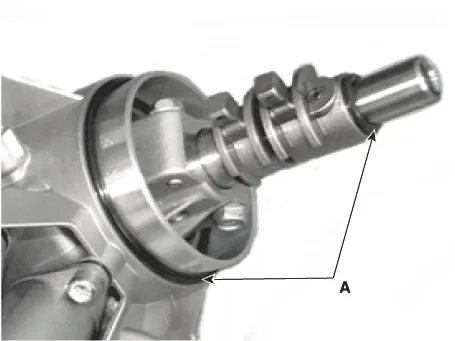
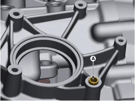

Specifications Specification Item Specification Rated voltage12VRod length79.0 - 80.0 mm (3.1102 - 3.
Description and operation Description• Components location : DCT (Dual Clutch Transmission)• Function The input shaft speed sensor is important in that it detects the input shaft RPM and sends this information to the Transmission Control Module (TCM).
Other information:
Hyundai Elantra (CN7) 2021-2026 Service Manual: License Lamps
Repair procedures Removal1.Disconnect the negative (-) battery terminal.2.Push the lock pin (B) and remove the license lamp (A).3.Disconnect the license lamp connector (A).4.Replace the bulb (A).Installation1.Connect the license lamp connector.2.Install the license lamp.
Hyundai Elantra (CN7) 2021-2026 Service Manual: Heater Core
Repair procedures Replacement1.Disconnect the negative (-) battery terminal. 2.Remove the heater and blower assembly.(Refer to Heater - "Heater Unit") 3.Remove the heater core cover (A) after loosening the mounting screws.4.Pull out the heater core (A) from the heater unit.
Categories
- Manuals Home
- Hyundai Elantra Owners Manual
- Hyundai Elantra Service Manual
- Fuse/Relay Panel Description. Engine compartment fuse panel
- Body (Interior and Exterior)
- Instrument Cluster
- New on site
- Most important about car
