Hyundai Elantra (CN7): Body Electrical System / Multifunction Switch
Hyundai Elantra (CN7) 2021-2026 Service Manual / Body Electrical System / Multifunction Switch
Components and components location
| Component |
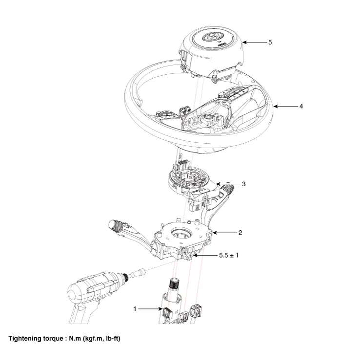
| 1. Steering column 2. Multifunction switch 3. Clock spring | 4. Steering wheel 5. Driver airbag module (DAB) |
Specifications
| Specifications |
|
Items
|
Specifications
| |
| Rated voltage | DC 12V | |
| Operating temperature range | -40 to +176°F (-40°C to +80°C) | |
| Quantity of standard load | Washer | Related current : 7A Blucking current : 15A Inrush current : 20A |
Repair procedures
| Removal |
| 1. | Disconnect the negative (-) battery terminal. |
| 2. | Remove the steering wheel. (Refer to Steering System - "Steering Wheel") |
| 3. | Remove the steering column upper and lower shrouds after loosening the screws. (Refer to Body - "Steering Column Shroud Panal") |
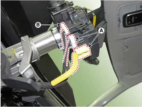
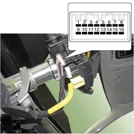
| 4. | Disconnect the multifunction switch connectors (B) and clock spring connector (A)
|
| 5. | Remove the clock spring (A).
|
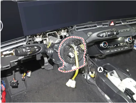
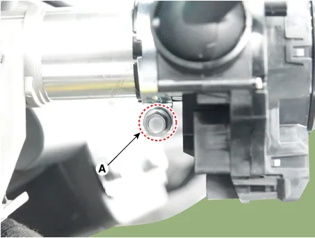
| 6. | Remove the multifunction switch assembly after loosening the clamp (A).
|
| Installation |
| 1. | Install the multifunction switch. |
| 2. | Install the clock spring. |
| 3. | Install the steering column upper and lower shrouds. |
| 4. | Install the steering wheel. |
| 5. | Connect the negative (-) battery terminal. |
| Inspection |
Multifunction Switch Inspection
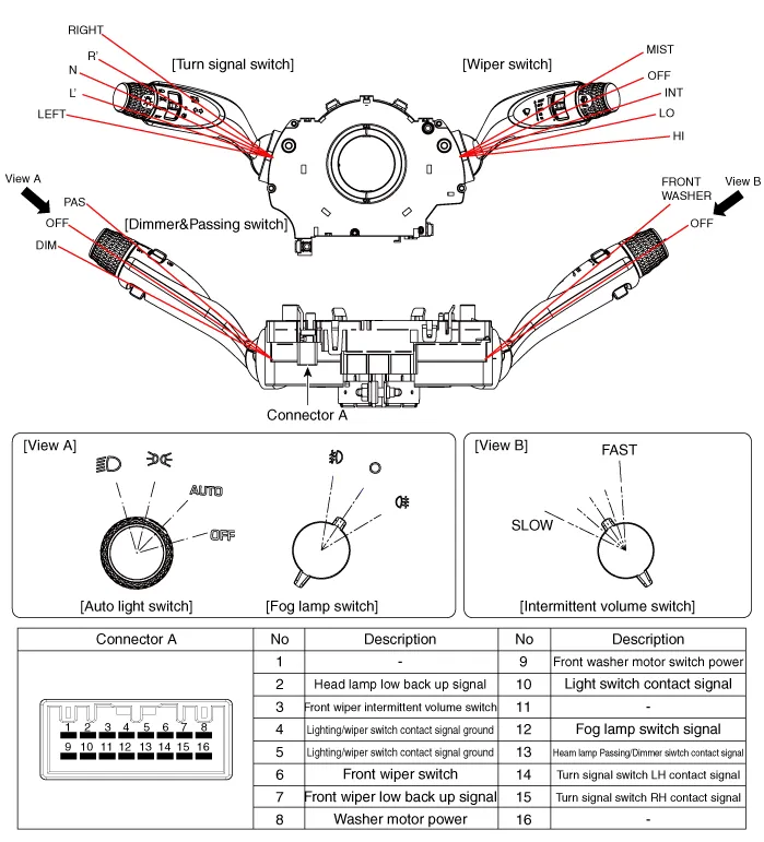
| 1. | Check for continuity between the terminals in each switch position according to the table.
[Left Handle Drive]
|
Inspection (With Diagnostic tool)
| 1. | In the body electrical system, failure can be quickly diagnosed by using the vehicle diagnostic system (Diagnostic tool). The diagnostic system (Diagnostic tool) provides the following information.
|
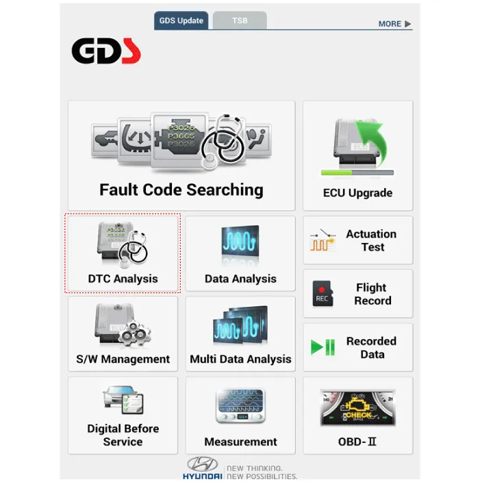
| 2. | If diagnose the vehicle by Diagnostic tool, select "DTC Analysis" and "Vehicle".
|
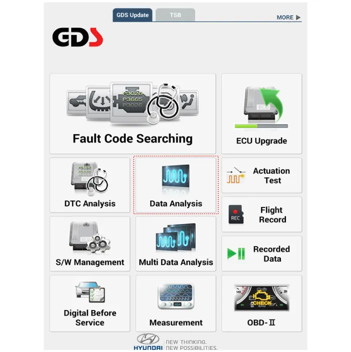
| 3. | If check current status, select the "Data Analysis" and "Car model".
|
| 4. | Select the 'IBU_BCM' to search the current state of the input/output data.
|
Special Service Tools Tool (Number and Name) Illustration Application RKE Battery Checker(09954-2P100)Measuring the RKE battery voltage.
Components and components location Component Location1. Horn switch2. Horn relay (Engine room compartment)3. Horn (Low pitch)4. Horn (High pitch)5. Clock spring Repair procedures Removal1.
Other information:
Hyundai Elantra (CN7) 2021-2026 Service Manual: Description and operating principle
Description and OperationWireless Power Charger SystemDuring ACC or IG ON, battery voltage is supplied to the wireless power charger system to transmit an output of 5 W to mobile phone. Mobile phones certified with the wireless charging standard WPC (Qi 1.
Hyundai Elantra (CN7) 2021-2026 Service Manual: Components and components location
C
Categories
- Manuals Home
- Hyundai Elantra Owners Manual
- Hyundai Elantra Service Manual
- Body Electrical System
- Suspension System
- Troubleshooting
- New on site
- Most important about car

Copyright © 2026 www.helantra7.com - 0.0162