Hyundai Elantra (CN7): Cylinder Block / Piston and Connecting Rod
Repair procedures
| Disassembly |
|

|

| 1. | Remove the engine and transaxle assembly. (Refer to Engine and Transaxle Assembly - "Engine and Transaxle Assembly") |
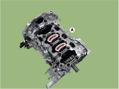
| 2. | Remove the rear oil seal. (Refer to Cylinder Block - "Rear Oil Seal") |
| 3. | Install the engine assembly to engine stand for disassembly. |
| 4. | Remove the cylinder head. (Refer to Cylinder Head Assembly - "Cylinder Head")
|
| 5. | Remove the oil filter body. (Refer to Lubrication System - "Oil Filter & Oil Cooler") |
| 6. | Remove the oil pump. (Refer to Lubrication System - "Oil Pump") |
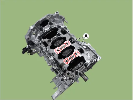
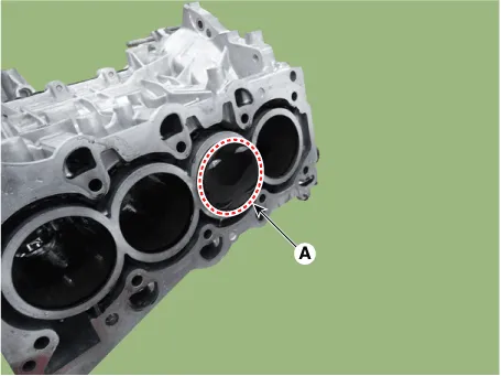
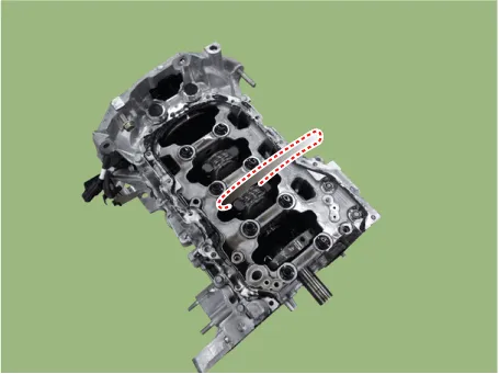
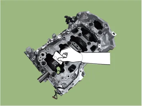
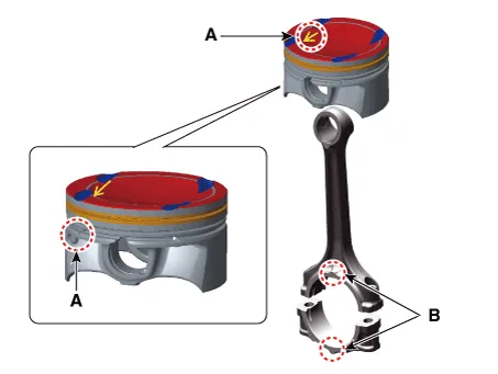
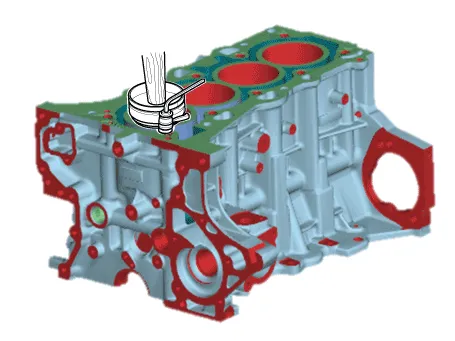
| 7. | Remove the piston and connecting rod assembly.
|
| 8. | Check fit between piston and piston pin. Try to move the piston back and forth on the piston pin. If any movement is felt, replace the piston and piston pin as a set. |
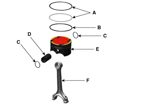
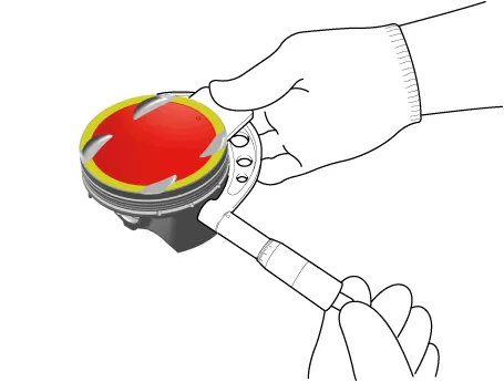
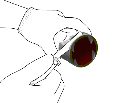
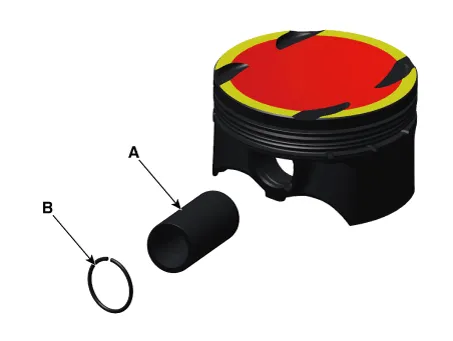
| 9. | Disassemble the piston rings.
|
| 10. | Disassemble the connecting rod from the piston.
|
| Inspection |
| 1. | Check the side clearance between piston and connecting rod. Using feeler gauge, measure the side clearance while moving the connecting rod back and forth.
|
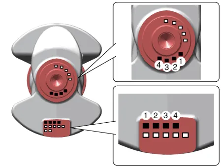
| 2. | Check the connecting rod bearing oil clearance.
| |||||||||||||||||||||||||||||||||||||||||||||||||||||||||||||||||||||||||||||||||||||||||||||||||||||||||||
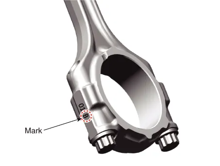
| 3. | Check the connecting rods.
|
| 1. | Clean the piston.
|
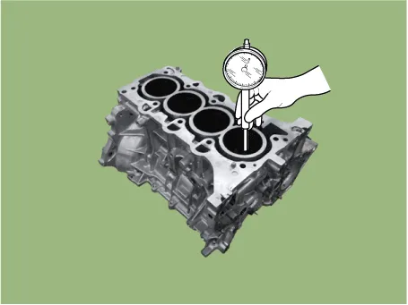
| 2. | Check the piston-to-cylinder clearance by calculating the difference between the cylinder bore inner diameter and the piston outer diameter.
|
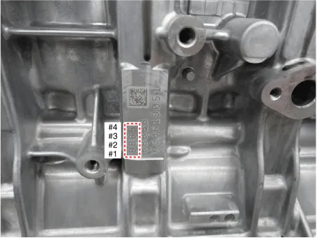
| 3. | Select the piston matching with cylinder bore class. (match classification mark)
|
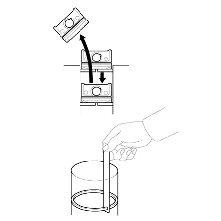
| 1. | Inspect the piston ring side clearance. Using a feeler gauge, measure the clearance between new piston ring and the wall of ring groove.
If the clearance is greater than maximum, replace the piston. |
| 2. | Inspect the piston ring end gap. To measure the piston ring end gap, insert a piston ring into the cylinder bore. Position the ring at right angles to the cylinder wall by gently pressing it down with a piston. Measure the gap with a feeler gauge. If the gap exceeds the specifications, replace the piston rings. If the gap is too large, recheck the cylinder bore inner diameter.
|
| 1. | Measure the outer diameter of piston pin
|
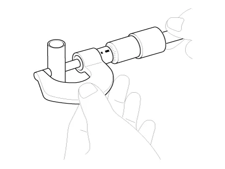
| 2. | Measure the piston pin-to-piston clearance.
|
| 3. | Check the difference between the piston pin outer diameter and the connecting rod small end inner diameter.
|
| Reassembly |
|
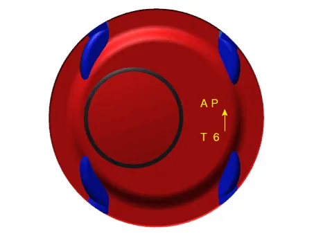
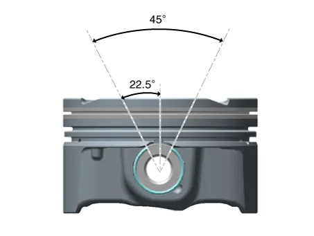
| 1. | Assemble the piston and the connecting rod.
|
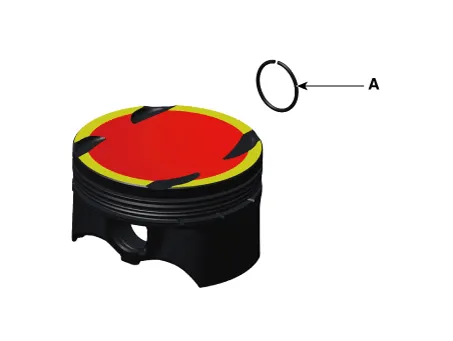
| 2. | Install the piston rings.
|

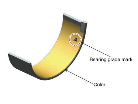
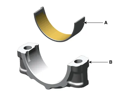
| 3. | Install the connecting rod bearings.
|
| 4. | Install the piston and connecting rod assembly.
|
| 5. | Assemble the other parts in the reverse order of disassembly. |
Components and components location Components1. Rear oil seal Repair procedures Replacement1.Remove the drive plate.(Refer to Cylinder Block - "Drive Plate")2.
Repair procedures Disassembly • Use fender covers to avoid damaging painted surfaces.• To avoid damage, unplug the wiring connectors carefully while holding the connector portion.
Other information:
Hyundai Elantra (CN7) 2021-2026 Service Manual: Start/Stop Button
Components and components location Component Repair procedures Removal1.Disconnect the negative(-) battery terminal.2.Remove the AVN Head unit.(Refer to Body Electrical System - "AVN(Audio Video Navigation) head unit")3.Loosen the mounting screws and remove the start/stop button (A).
Hyundai Elantra (CN7) 2021-2026 Service Manual: Heater & A/C Control Unit (Manual)
Components and components location Components[This illustration shows the LHD type. RHD type is symmetrical.][Connector A] Pin No Function Pin No Function 1Low (Register specifications)4Middle Low (Register specifications)2Common (Register
Categories
- Manuals Home
- Hyundai Elantra Owners Manual
- Hyundai Elantra Service Manual
- Body (Interior and Exterior)
- Body Electrical System
- Maintenance
- New on site
- Most important about car
