Hyundai Elantra (CN7): Fuses And Relays / Relay Box (Passenger Compartment)
Repair procedures
| Fuse Inspection |
| 1. | Check that the fuse holders are loosely held and that the fuses are securely fixed by the holders. |
| 2. | Check that each fuse circuit has the exact fuse capacity. |
| 3. | Check the fuses for any damage.
|

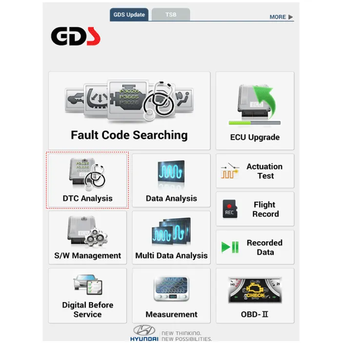
| 1. | In the body electrical system, failure can be quickly diagnosed by using the vehicle diagnostic system (Diagnostic tool). The diagnostic system(Diagnostic tool) provides the following information.
|
| 2. | If diagnose the vehicle by Diagnostic tool, select "DTC Analysis" and "Vehicle".
|
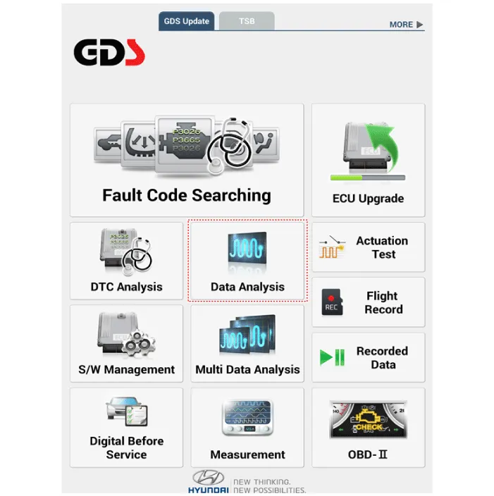
| 3. | If check current status, select the "Data Analysis" and "Car model".
|
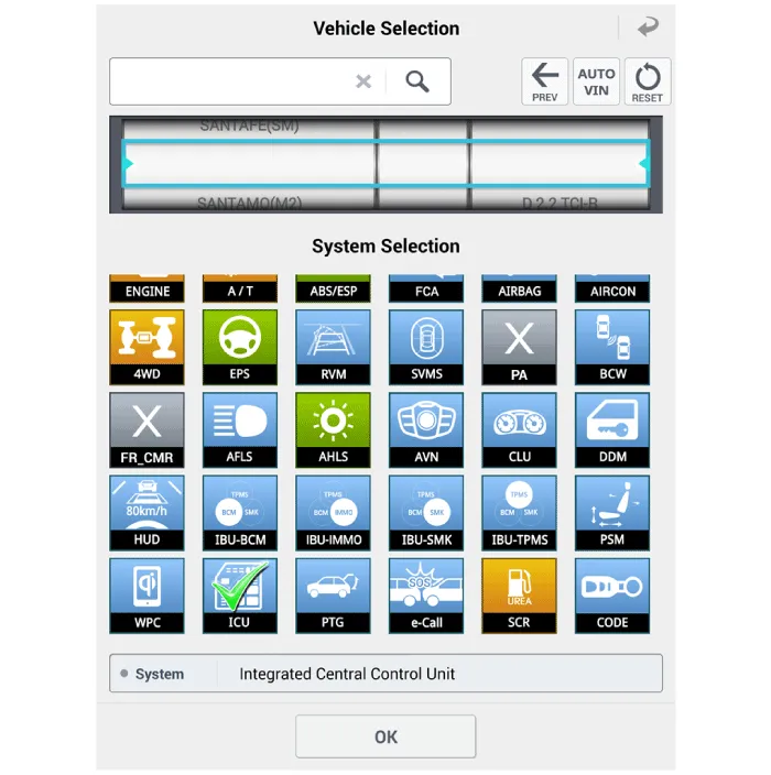
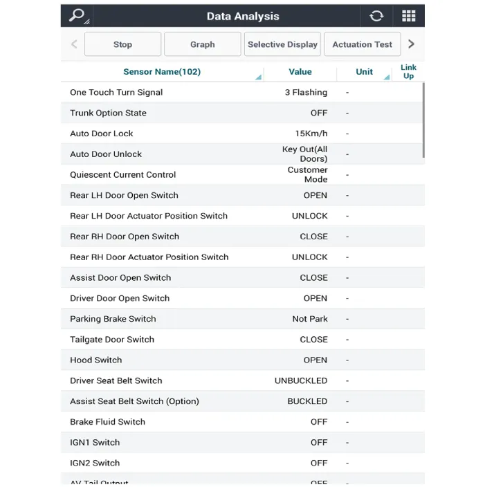
| 4. | Select the 'ICU' to search the current state of the input/output data.
|
| Removal |
| 1. | Disconnect the negative (-) battery terminal. |
| 2. | Remove the crash pad lower panel. (Refer to Body - "Crash Pad Lower Panel") |
| 3. | Disconnect the connectors from the fuse side of the ICU.
|
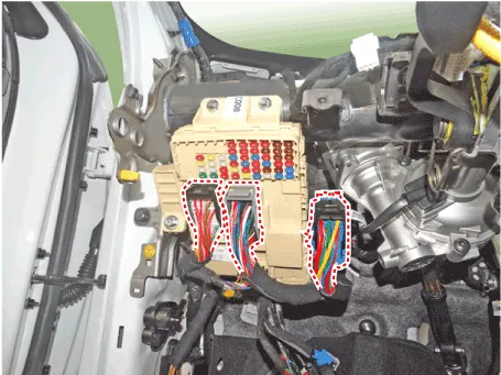
| 4. | Remove the ICU (A) after loosening the mounting nuts.
|

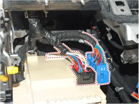
| 5. | Disconnect the connectors from the back side of the ICU.
|
| Installation |
| 1. | Install the smart junction box. |
| 2. | Install the crash pad lower panel. |
| 3. | Connect the negative (-) battery terminal. |
| 4. | Check that all system operates normally. |
Repair procedures Inspection1.Disconnect the negative (-) battery terminal.2.Pull out the relay from the engine compartment relay block.Power Relay (Type A) Check for continuity between the terminals.
Other information:
Hyundai Elantra (CN7) 2021-2026 Service Manual: Description and operation
Description and OperationBlcok Diagram • This system monitors the driving situations through the radar and the camera. Thus, for a situation out of the sensing range, the system may not normally operate. The System may be limited when : • The radar sensor or camer
Hyundai Elantra (CN7) 2021-2026 Service Manual: Desctiprion and operation
DescriptionADAS_PRK is a unit that controls the functions required for ADAS parking. If the ADAS_PRK is applied, the parking distance warning function is also controlled by the ADAS_PRK.System FunctionParking Collision-Avoidance Assist (PCA)PCA is a parking safety system that assists in collision warning and emergency braking in the event of a coll
Categories
- Manuals Home
- Hyundai Elantra Owners Manual
- Hyundai Elantra Service Manual
- Body (Interior and Exterior)
- Maintenance
- Suspension System
- New on site
- Most important about car
