Hyundai Elantra (CN7): Front Suspension System / Components and components location
Hyundai Elantra (CN7) 2021-2026 Service Manual / Suspension System / Front Suspension System / Components and components location
| Components |
[A type]
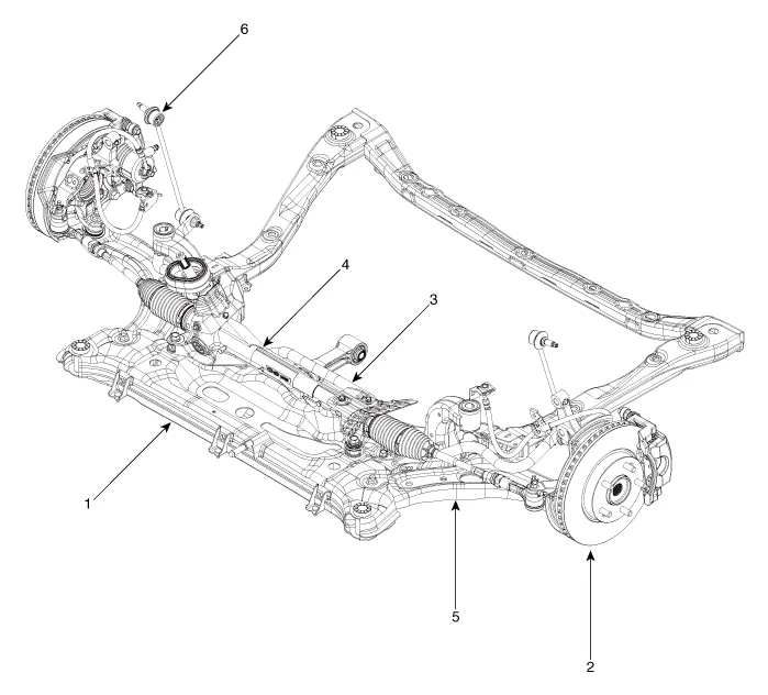
| 1. Front sub frame 2. Front axle 3. Front stabilizer bar | 4. Steering gearbox 5. Front lower arm 6. Front stabilizer bar link |
[B type]
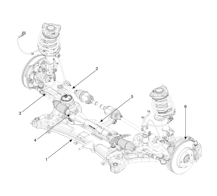
| 1. Sub frame 2. Drive shaft 3. Lower arm | 4. Steering gearbox 5. Stabilizer bar 6. Front axle assembly |
Components and components location Components 1. Insulator cap2. Lock nut3. Insulator & sturt bearing4. Bumper rubber5. Dust cover6. Coil spring7.
Other information:
Hyundai Elantra (CN7) 2021-2026 Service Manual: Components and positions
C
Hyundai Elantra (CN7) 2021-2026 Service Manual: Auto Defoging Actuator
Description and operation DescriptionThe auto defogging sensor is installed on front window glass. The sensor judges and sends signal if moisture occurs to blow out wind for defogging. The air conditioner control module receives a signal from the sensor and restrains moisture and eliminates defog by the intake actuator, A/C, auto defogging actua
Categories
- Manuals Home
- Hyundai Elantra Owners Manual
- Hyundai Elantra Service Manual
- Drive Mode
- Brake bleeding procedures
- Vehicle Information
- New on site
- Most important about car

Copyright © 2026 www.helantra7.com - 0.0176