Hyundai Elantra (CN7): Cylinder Head Assembly / CVVD Assembly
Description and operation
| Description |

| Operation Principle |
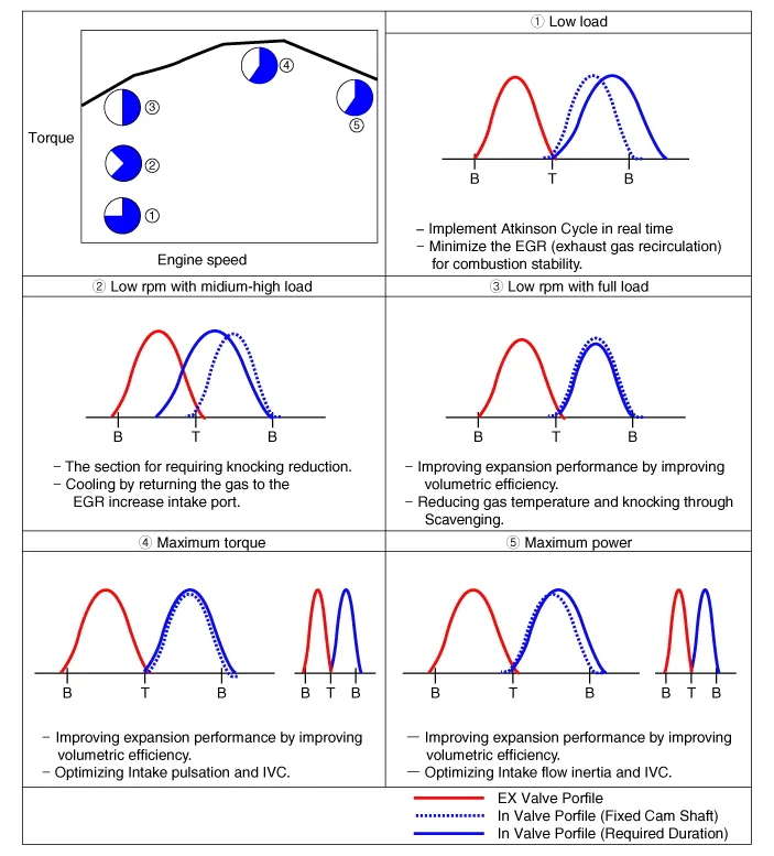
| Optimum Valve Timing by Engine Load |
Repair procedures
| Removal |
| 1. | Disconnect the battery negative terminal. |
| 2. | Remove the cylinder head cover. (Refer to Cylinder Head Assembly - "Cylinder Head Cover") |
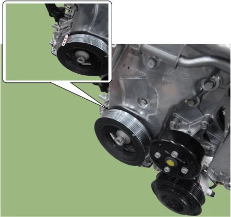
| 3. | Turn the crankshaft damper pulley so that No. 1 piston is at top dead center.
|

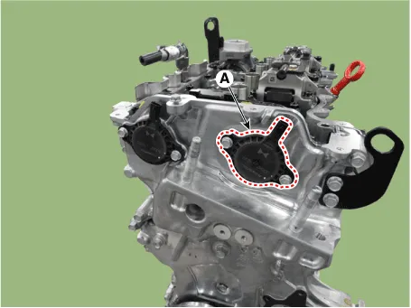
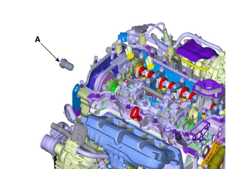
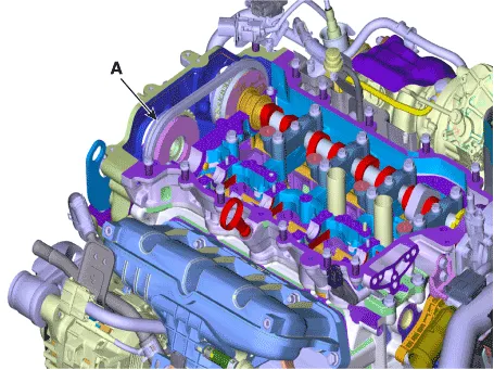
| 4. | Remove the Intake variable force solenoid (VFS) valve (A).
|
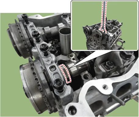
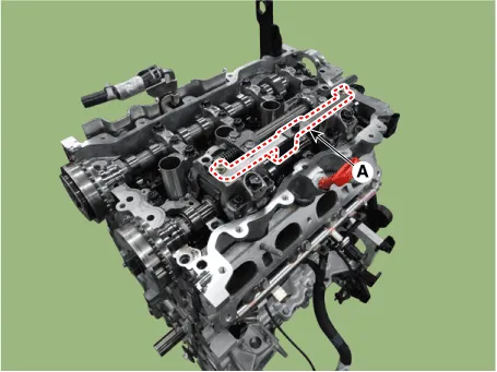
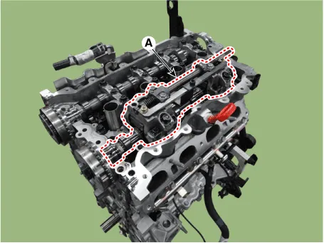
| 5. | Remove the cam to cam guide (A).
|

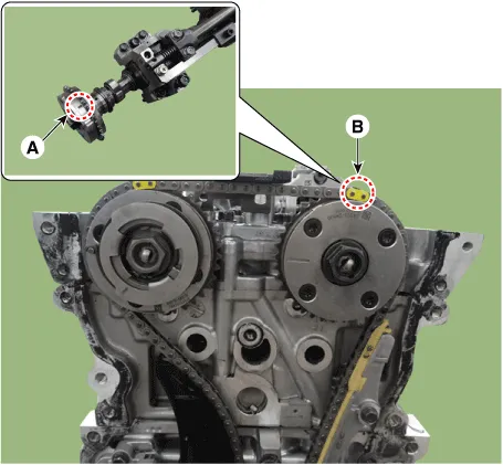
| 6. | Reomve the front bearing cap (A) and intake camshaft bearing caps (B).
|

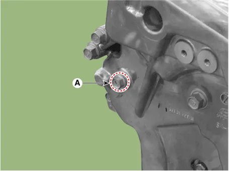
| 7. | Remove the service hole bolt (A).
|
| 8. | Remove the engine mounting support bracket. (Refer to Engine and Transaxle Assembly - "Engine Mounting") |
| 9. | Lift the engine using the jack to obtain space. |
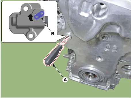
| 10. | Release the lock by putting down rachet plate (B) of timing chain tensioner with using back of tiny awl (A).
|

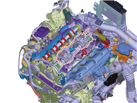
| 11. | Remove the intake oil control valve (OCV) & center bolt (A).
|

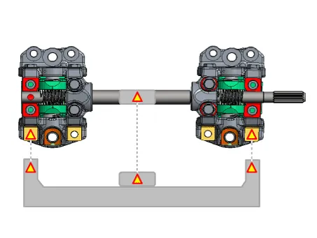
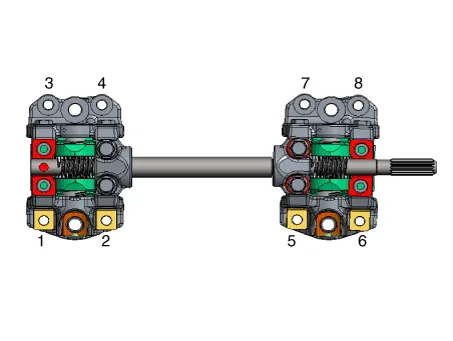
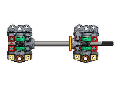
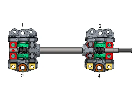
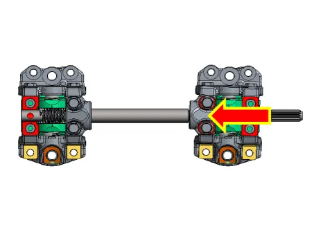
| 12. | Remove the CVVD assembly.
When Using the CVVD fixture
When not using the CVVD fixture
|
| 13. | Remove the Intake CVVT (A).
|
| Installation |
| 1. | Install the Intake CVVT (A).
|
| 2. | Install the CVVD assembly (A).
|


| 3. | Install the intake OCV & center bolt (A).
|
| 4. | Compress the timing chain tensioner piston.
|


| 5. | Install the front bearing cap and camshaft bearing cap
|
| 6. | Remove the fine gimlets (A) that hold the timing chain tensioner.
|
| 7. | When installing the timing chain, be sure that the timing mark (A) of each sprocket is matched with the timing mark (B) (color link) of the timing chain. [Intake CVVT Timing Mark]
[Exhaust CVVT Timing Mark]
|
| 8. | Install the cam to cam guide (A).
|
| 9. | Install the intake variable force solenoid (VFS) valve (A).
|
| 10. | Install the cylinder head cover. (Refer to Cylinder Head Assembly - "Cylinder Head Cover") |
Repair procedures Removal 1.Disconnect the battery negative terminal.2.Remove the cylinder head cover. (Refer to Cylinder Head Assembly - "Cylinder Head Cover")3.
Repair procedures Removal • Use Fender cover to avoid damaging painted surfaces.• To avoid damaging the cylinder head, wait until the engine coolant temperature drops below normal temperature before removing it.
Other information:
Hyundai Elantra (CN7) 2021-2025 Service Manual: A/C Pressure Transducer
Description and operation DescriptionThe A/C Pressure Transducer (APT) converts the pressure value of high pressure line into voltage value after measuring it. By converted voltage value, engine ECU controls the cooling fan by operating it high speed or low speed.
Hyundai Elantra (CN7) 2021-2025 Service Manual: Smart Cruise Control (SCC) Switch
Schematic diagrams Circuit DiagramTRIP / SCC / LFA Repair procedures Inspection1.Check for resistance between terminals in each switch position (LH).[LH : Audio + Hands free] Switch Resistance (±5%) SEEK Up430 ΩSEEK Down1.
Categories
- Manuals Home
- Hyundai Elantra Owners Manual
- Hyundai Elantra Service Manual
- Emergency situations
- Drive Mode
- General Tightening Torque Table. General information
- New on site
- Most important about car
