Hyundai Elantra (CN7): Body (Interior and Exterior) / Fender
Components and components location
| Component Location |

| 1. Fender assembly |
Repair procedures
| Replacement |
|

| 1. | Remove the front bumper. (Refer to Front Bumper - "Front Bumper Assembly") |
| 2. | Remove the head lamps. (Refer to Body Electrical System - "Head Lamps") |
| 3. | Remove the front wheel guard. (Refer to Body Side Molding - "Front Wheel Guard") |
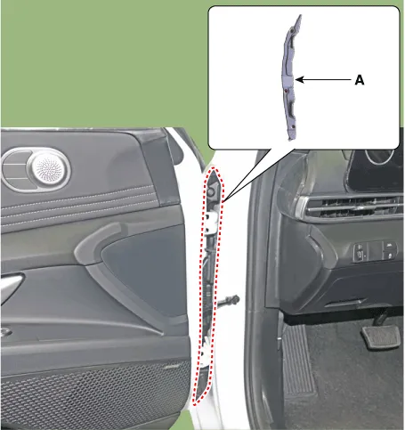
| 4. | Remove the front bumper side mounthing bracket (A) after loosening the bolts.
|
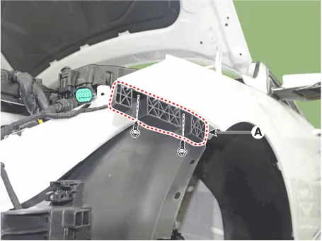
| 5. | Loosen the mounting clips and remove the insulator cover (A).
|
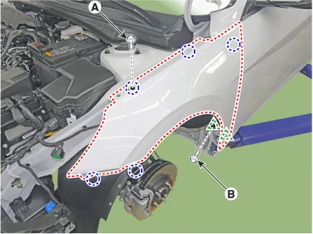
| 6. | After loosening the mounting bolts, remove the fender assembly.
|
| 7. | To install, reverse the removal procedure.
|

Special Service Tools Tool (Number and name) Illustration Use 09880 - 4F000Hog ring clip installerHog ring clip installation
Repair procedures Adjustment1.After loosening the hinge (A) mounting bolt, adjust the hood (B) by moving it up and down or from side to side and tighten the bolt.
Other information:
Hyundai Elantra (CN7) 2021-2026 Service Manual: High Mounted Stop Lamp
Repair procedures Removal1.Disconnect the negative (-) battery terminal.2.Remove the rear package tray trim.(Refer to Body - "Rear Package Tray Trim")3.Loosen the mounting screws and remove the high mounted stop lamp (A).Installation1.Install the high mounted stop lamp.
Hyundai Elantra (CN7) 2021-2026 Service Manual: Power Mosfet
Description and operation DescriptionIt is installed to the DATC and adjusts the fan rpm by precisely controlling the voltage applied to the blower motor. Repair procedures Inspection1.Manually operate the control switch and measure the voltage of the blower motor.
Categories
- Manuals Home
- Hyundai Elantra Owners Manual
- Hyundai Elantra Service Manual
- Troubleshooting
- Rear Seats
- Function settings
- New on site
- Most important about car
