Hyundai Elantra (CN7): Body (Interior and Exterior) / Front Bumper
Components and components location
| Components |
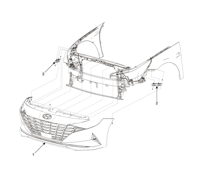
| 1. Front bumper assembly 2. Front bumper side bracket [LH] | 3. Front bumper side bracket [RH] |
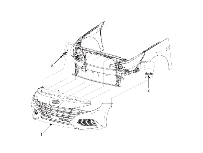
| 1. Front bumper assembly 2. Front bumper side bracket [LH] | 3. Front bumper side bracket [RH] |
Front Bumper Assembly
Components and components location
| Component Location |
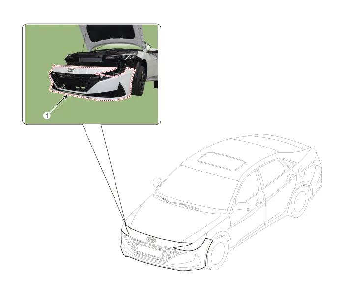
| 1. Front bumper Assembly |
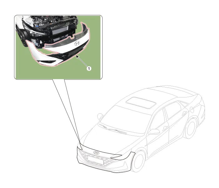
| 1. Front bumper assembly |
Repair procedures
| Replacement |
|

|

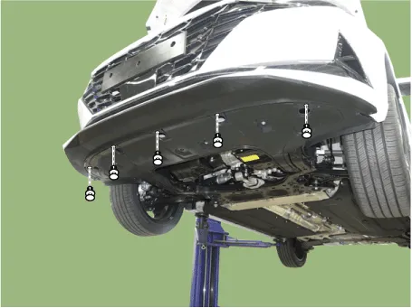
| 1. | Loosen the front bumper upper mounting clips.
|

| 2. | Loosen the front bumper lower mounting clips.
|
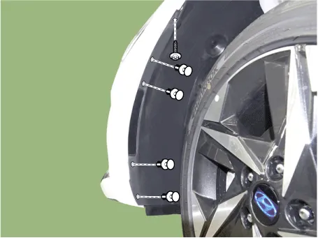
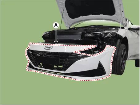
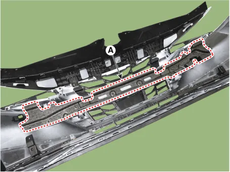
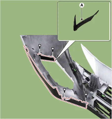
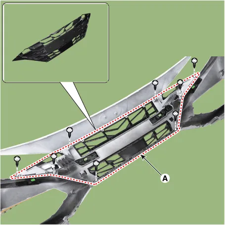
| 3. | After loosening the pin-type retainers and screws on the side of front bumper (A), detach the side part of front bumper.
|
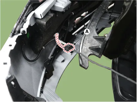
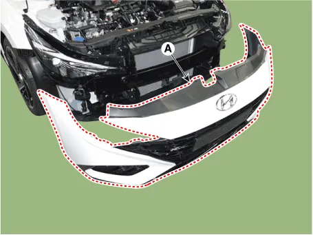
| 4. | Disconnect the front bumper main connector (A).
|
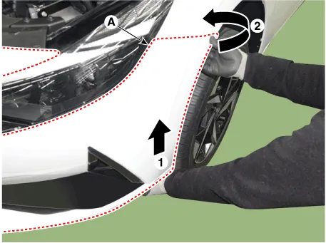
| 5. | Remvoe the front bumper assembly (A). [General type]
[N Line]
|
| 6. | To install, reverse the removal procedure.
|

Radiator Grill
Components and components location
| Component Location |
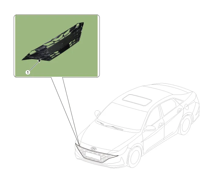
| 1. Radiator grill |
Repair procedures
| Replacement |
|
|
| 1. | Remove the front bumper assembly. (Refer to Front Bumper - "Front Bumper Assembly") |
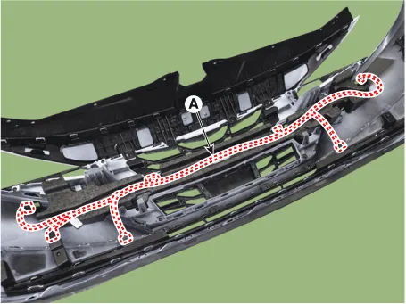
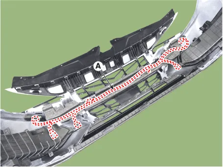
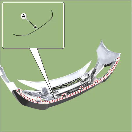
| 2. | Detach the wiring (A) mounted on the front bumper assembly and energy absober.
|
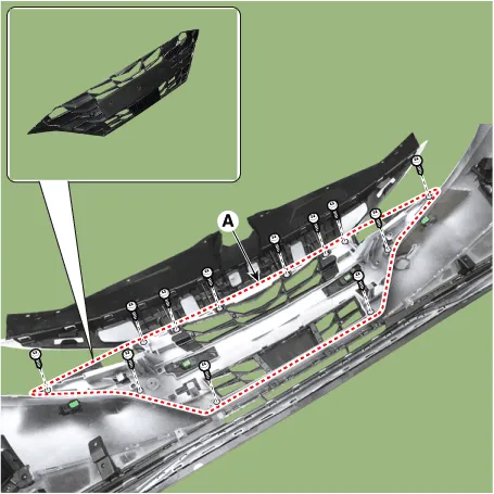
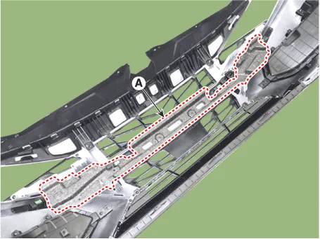
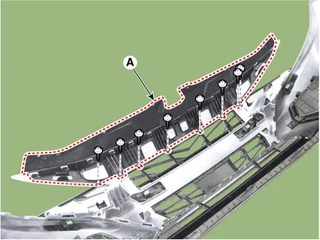
| 3. | Remove the front bumper energy absorber (A).
|
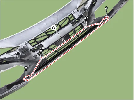
| 4. | Loosen the mounting screws, remove the radiator grill (A).
|
| 5. | To install, reverse the removal procedure.
|
|
|
| 1. | Remove the front bumper assembly. (Refer to Front Bumper - "Front Bumper Assembly") |
| 2. | Detach the wiring (A) mounted on the front bumper assembly and energy absober.
|
| 3. | Remove the front bumper energy absorber (A).
|
| 4. | Loosen the mounting screws, remove the radiator grill upper cover (A).
|
| 5. | Remove the front bumper lip (A).
|
| 6. | Loosen the mounting screws, remove the front bumper grill (A).
|
| 7. | Loosen the mounting screws, remove the front bumper molding (A).
|
| 8. | Loosen the mounting screws, remove the radiator grill (A).
|
| 9. | To install, reverse the removal procedure.
|
Repair procedures Replacement • When removing with a flat - tip screwdriver or remover, wrap protective tape around the tools to prevent damage to components.
Components and components location Component Location [General type]1. Rear bumper assembly2. Rear bumper under cover [LH]3. Rear bumper under cover [RH]4.
Other information:
Hyundai Elantra (CN7) 2021-2026 Service Manual: Wireless Power Charging Unit
Components and positions Components Circuit diagram Circuit Diagram Repair procedures Removal • Handling wireless charging system parts by wet hands may cause electric shock. 1.Disconnect the negative (-) battery terminal.
Hyundai Elantra (CN7) 2021-2026 Service Manual: Condenser
Components and components location Components Location[General type]1. Condenser[N Line]1. Condenser Repair procedures Inspection1.Check the condenser fins for clogging and damage. If clogged, clean them with water, and blow them with compressed air.
Categories
- Manuals Home
- Hyundai Elantra Owners Manual
- Hyundai Elantra Service Manual
- Troubleshooting
- Engine Mechanical System
- General Tightening Torque Table. General information
- New on site
- Most important about car
