Hyundai Elantra (CN7): Body Electrical System / Ignition Switch Assembly. Repair procedures
Repair procedures
| Replacement |
| 1. | Disconnect the negative (-) battery terminal. |
| 2. | Remove the crash pad lower panel. (Refer to Body - "Crash Pad") |
| 3. | Remove the steering column upper & Lower shroud. |
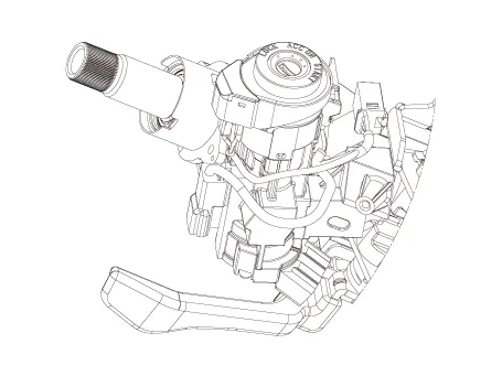
| 4. | Remove the ignition switch and disconnecting the Key Warning / immobilizer connector.
|
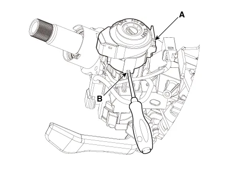
| 5. | If it is necessary to remove the key lock cylinder (A), remove the key lock cylinder (A) after pushing lock pin (B) with key ACC.
|
| 6. | Installation is the reverse of removal procedure. |
| Inspection |
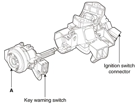
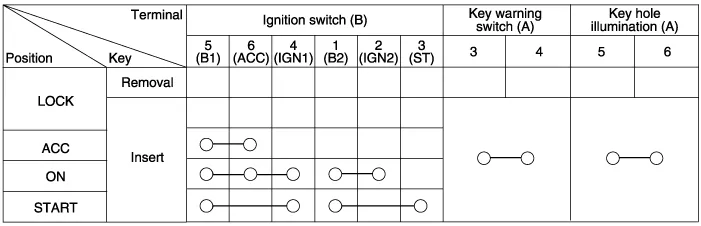
| 1. | Disconnect the ignition switch connector (A) and key warning switch connector (B) from under the steering column.
|

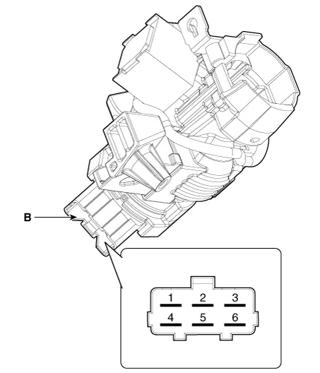
| 2. | Check for continuity between the terminals. |
| 3. | If continuity is not specified, replace the switch.
|
Repair procedures Removal1.Disconnect the negative (-) battery terminal.2.Remove the crash pad lower panel.(Refer to Body - "Crash Pad Lower Panel")3.
Other information:
Hyundai Elantra (CN7) 2021-2026 Service Manual: Climate Control Air Filter
Description and operation Description The climate control air filter is located in the blower unit. It eliminates foreign materials and odor. The particle filter performs a role as an odor filter as well as a conventional dust filter to ensure comfortable interior environment.
Hyundai Elantra (CN7) 2021-2026 Service Manual: Front Radar Unit
Components and components location Components Location1. Front rader unit Specifications Specification Item Specification Power supply (V)12Operation voltage (V)9 - 16 Schematic diagrams Circuit DiagramTerminal function Pin No Te
Categories
- Manuals Home
- Hyundai Elantra Owners Manual
- Hyundai Elantra Service Manual
- Troubleshooting
- Body Electrical System
- Engine Mechanical System
- New on site
- Most important about car
