Hyundai Elantra (CN7): Engine Control System / Injector
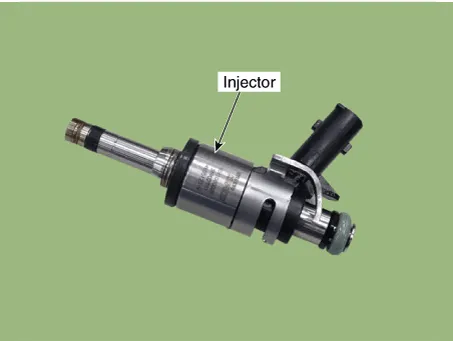
Description and operation
| Description |
Specifications
| Specification |
|
Item
|
Specification
|
| Coil Resistance (Ω) | 1.19 - 1.31 [20°C (68°F)] |
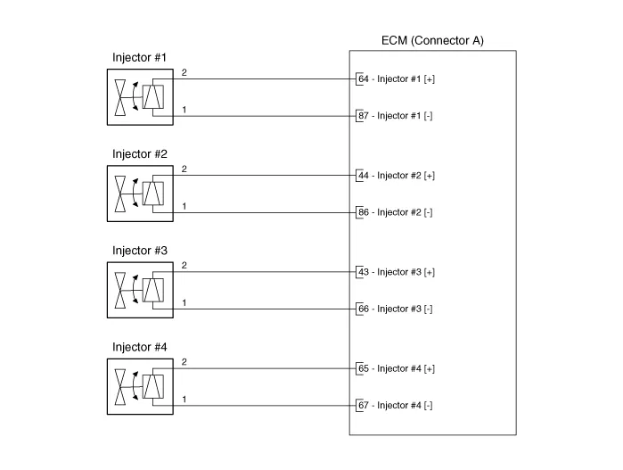
Schematic diagrams
| Circuit Diagram |
Repair procedures
| Inspection |
| 1. | Turn ignition switch OFF. |
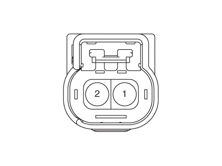
| 2. | Disconnect injector connector. |
| 3. | Measure resistance between injector terminals 1 and 2. |
| 4. | Check that the resistance is within the specification.
|
| Removal |
| 1. | Turn ignition switch OFF and disconnect the battery negative (-) terminal. |
| 2. | Release the residual pressure in fuel line. (Refer to Fuel Delivery System - "Release Residual Pressure in Fuel Line")
|

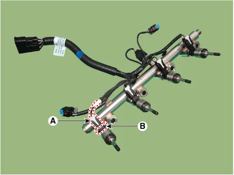
| 3. | Remove the delivery pipe & injector assembly. (Refer to Fuel Delivery System - "Delivery Pipe") |
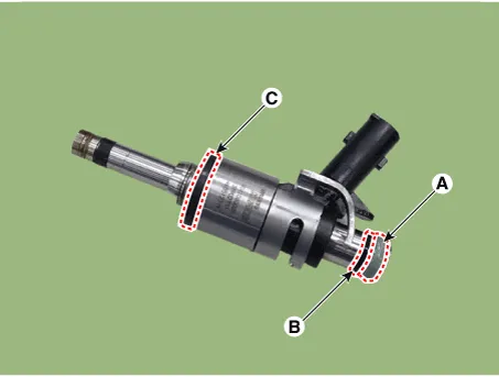
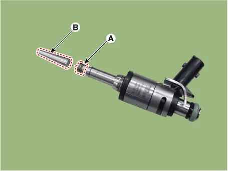
| 4. | Remove the connector (A) and fixing clip (B), and then separate the injector from the delivery pipe.
|
| Installation |
| 1. | Install in the reverse order of removal.
|

| Replacement |
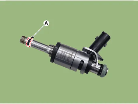
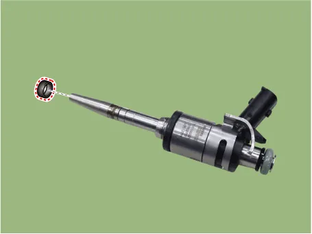
| 1. | Remove the combustion seal (A) with a wire cutter.
|
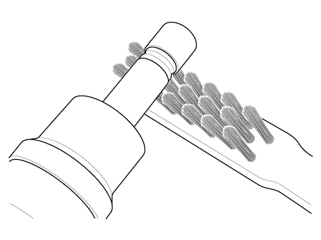
| 2. | Before the assembly of the sealing ring the groove must be cleaned using a clean cloth. Any coking of the injector sealing surface must be carefully removed with a brass-wire brush.
|
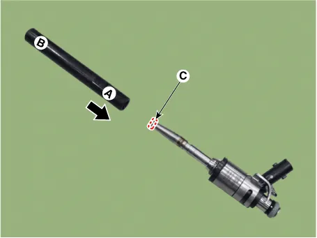
| 3. | Place the seal installing guide (B) (SST No. : 09353-2B000) on the tip of the injector not to damage the injector tip (A). Push the sealing ring (C) with thumb and index finger over the conical assembly tool until it snaps into the groove. The complete assembly must not take longer than 2 to 3 seconds.
|
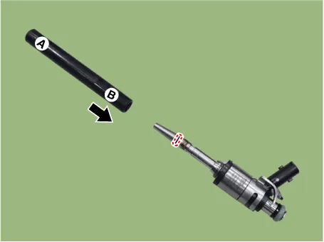
| 4. | To size the sealing ring the injector is first introduced into the sizing tool (A) (SST No. : 09353-2B000) and then pressed and at the same time rotated 180° into the sizing tool.
|
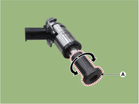
| 5. | Pull the injector out of the sizing tool by turning it in the reverse direction to that used for the press-in process.
|
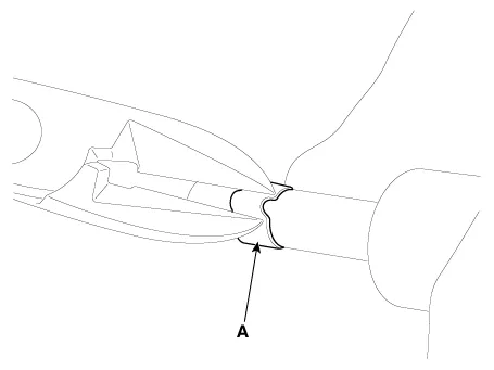
| 6. | Check the combustion seal (A) installation.
|
Description and operation DescriptionInstalled on the delivery pipe, the Rail Pressure Sensor (RPS) measures the instantaneous fuel pressure in the delivery pipe.
Description and operation DescriptionAmbient Temperature Sensor (ATS) is installed on the front-end module and senses the ambient temperature. This sensor is exposed to the ambient air temperature in front of the radiator.
Other information:
Hyundai Elantra (CN7) 2021-2025 Service Manual: Auto Defoging Actuator
Description and operation DescriptionThe auto defogging sensor is installed on front window glass. The sensor judges and sends signal if moisture occurs to blow out wind for defogging. The air conditioner control module receives a signal from the sensor and restrains moisture and eliminates defog by the intake actuator, A/C, auto defogging actua
Hyundai Elantra (CN7) 2021-2025 Service Manual: Description and operation
Description and OperationBlcok Diagram • This system monitors the driving situations through the radar and the camera. Thus, for a situation out of the sensing range, the system may not normally operate. The System may be limited when : • The radar sensor or camer
Categories
- Manuals Home
- Hyundai Elantra Owners Manual
- Hyundai Elantra Service Manual
- Engine Electrical System
- Body Electrical System
- Heating, Ventilation and Air Conditioning
- New on site
- Most important about car
