Hyundai Elantra (CN7): Intake And Exhaust System / Intercooler
Repair procedures
| Removal and Installation |
| 1. | Disconnect the battery negative terminal. |
| 2. | Remove the engine room under cover. (Refer to Engine and Transaxle Assembly - "Engine Room Under Cover") |
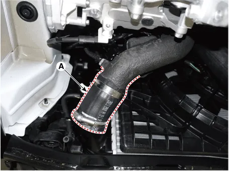
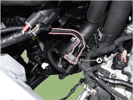
| 3. | Disconnect the intercooler inlet hose (A).
|

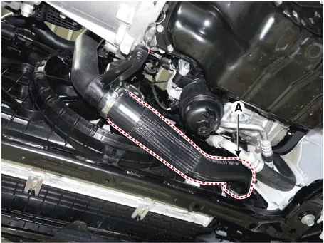
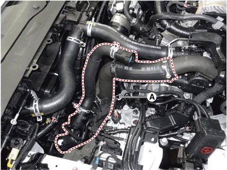
| 4. | Disconnect the intercooler outlet hose (A).
|
| 5. | Remove the front bumper cover. (Refer to Body - "Front Bumper Cover") |
| 6. | Remove the intercooler air guard (A).
|

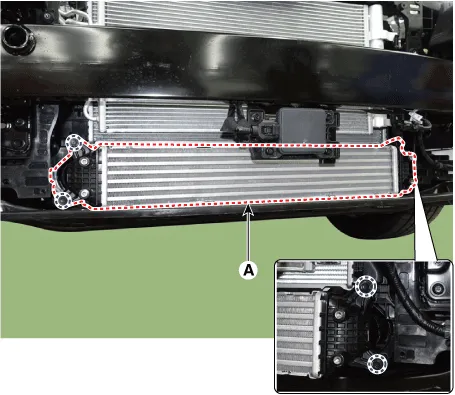
| 7. | Remove the intercooler (A).
|
| 8. | Install in the reverse order of removal. |
| 1. | Disconnect the battery negative terminal. |
| 2. | Remove the air duct and air cleaner assembly. (Refer to Intake and Exhaust System - "Air Cleaner") |
| 3. | Remove the battery and battery tray. (Refer to Engine Electrical System - "Battery") |
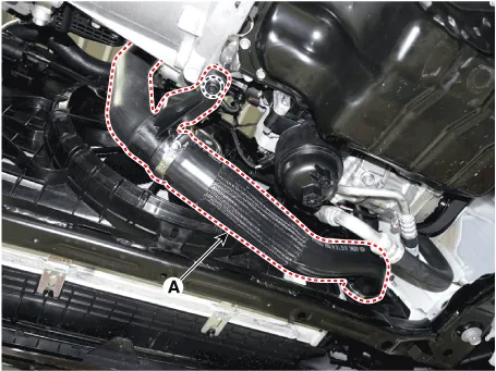
| 4. | Remove the intercooler inlet hose and pipe.
|
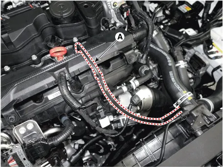
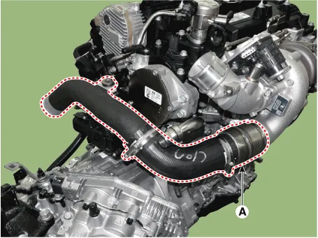
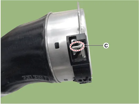
| 5. | Remove the intercooler hose & pipe (A).
|
| 6. | Install in the reverse order of removal. |
| 1. | Disconnect the battery negative terminal. |
| 2. | Remove the engine room under cover. (Refer to Engine and Transaxle Assembly - "Engine Room Under Cover") |
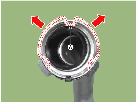
| 3. | Remove the intercooler outlet hose and pipe.
|


| 4. | Install in the reverse order of removal. |
Repair procedures Removal and Installation1.Remove the Turbocharger & Exhaust Manifold.(Intake And Exhaust System - "Exhaust Manifold")On-vehicle InspectionTurbocharger Diagnostic Flow If any problem related with turbocharger, such as lack of engine power, poor acceleration, abnormal engine noise or oil leaks, may occur, check the turbocharger according to the procedure as follows.
Components and components location Components1. Front muffler2. Catalytic converter & Center muffler3. Rear muffler4. Gasket5. Hanger Repair procedures Removal and InstallationFront Muffler1.
Other information:
Hyundai Elantra (CN7) 2021-2025 Service Manual: Immobilizer Control Unit
Components and components location Components (1)With Smart KeyConnector Pin Information Pin no Connector A Connector B Connector C Connector D Connector E 1ESCL
Hyundai Elantra (CN7) 2021-2025 Service Manual: Desctiprion and operation
DescriptionADAS_PRK is a unit that controls the functions required for ADAS parking. If the ADAS_PRK is applied, the parking distance warning function is also controlled by the ADAS_PRK.System FunctionParking Collision-Avoidance Assist (PCA)PCA is a parking safety system that assists in collision warning and emergency braking in the event of a coll
Categories
- Manuals Home
- Hyundai Elantra Owners Manual
- Hyundai Elantra Service Manual
- Towing
- Body Electrical System
- Emergency situations
- New on site
- Most important about car
