Hyundai Elantra: Manual Transaxle System / Manual Transaxle
Hyundai Elantra (CN7) 2021-2025 Service Manual / Manual Transaxle System / Manual Transaxle System / Manual Transaxle
Components and components location
| Components |
| 1. Control shaft complete 2. Control cable bracket 3. Back-up lamp switch | 4. Manual transaxle bracket 5. Concentric slave cylinder |
Repair procedures
| Removal |
| 1. | Remove the air cleaner assembly and air duct. (Refer to Engine Mechanical System - "Air Cleaner") |
| 2. | Remove the battery and battery tray. (Refer to Engine Electrical System - "Battery") |
| 3. | Loosen the bolt and then separate the engine wiring (A).
|
| 4. | Disconnect the back up lamp switch connector (A).
|
| 5. | Remove the control cable bracket and control cable at the same time.
|
| 6. | Loosen the bolt and then separate the ground line (A).
|
| 7. | Remove the snap pin (A) and the clutch hose (B).
|
| 8. | Remove the starter motor mounting bolts (A) and the transaxle upper mounting bolts (B).
|
| 9. | Assemble the engine support fixture use a (Beam SST No.: 09200 - 3N000, Adapter SST No.: 09200-4X000, Engine fixture adapter (rear) SST No.: 09200-L1100, Engine fixture adapter (front) SST No.: 09200-L1200. |
| 10. | Using the engine support fixture(A), hold the engine and transaxle assembly safely.
|
| 11. | Remove the dust cover (A).
|
| 12. | Loosen the transaxle bracket support mounting bolts (A).
|
| 13. | Loosen the bolts and then removing the transaxle bracket (A).
|
| 14. | Remove the under cover. (Refer to Engine Mechanical System - "Engine Room Under Cover") |
| 15. | After loosening the drain plug (A), drain the manual transaxle fluid, then install the drain plug.
|

| 16. | Loosen the bolts and then removing the wiring bracket (A, B).
|
| 17. | Loosen the bolts (A, B) and then removing the roll rod assembly (C).
|
| 18. | Loosen the bolts and then removing the roll rod support bracket (A).
|
| 19. | Remove the drive shaft assembly. (Refer to Driveshaft and axle (2WD-FF) - "Front Driveshaft") |
| 20. | Remove the lower mounting bolts (A), (B) of lower part of the transaxle, and the left side cover and remove the transaxle assembly by supporting it with a jack.
|
| Installation |
|

| 1. | To install, reverse the removal procedures. |
| 2. | Injection the manual transaxle fluid. (Refer to Manual Transaxle System - "Manual Transaxle Fluid") |
| 3. | Perform bleeding air procedure in concentric slave cylinder after pouring the brake fluid. (Refer to Clutch System - "Repair Procedures") |

 Back-up Lamp Switch
Description and operation
Description
Component location : Control shaft complete
Operation principle : Back up lamp switch is pushed by the reverse lug sliding when select arm, and switches the back up lamp...
Other information:
Hyundai Elantra (CN7) 2021-2025 Service Manual: Description and operation
Description of ESPESP recognizes critical driving conditions, such as panic reactions in dangerous situations, and stabilizes the vehicle by wheel-individual braking and engine control intervention.ESP adds a further function known as Active Yaw Control (AYC) to the ABS, TCS, EBD and ESP functions...
Hyundai Elantra (CN7) 2021-2025 Service Manual: Engine Cover
Repair procedures Removal and Installation1.Remove the engine cover (A).2.Installation is reverse order of removal..
Categories
- Manuals Home
- 7th Gen Hyundai Elantra Owners Manual
- 7nd Gen Hyundai Elantra Service Manual
- Dimensions, Engine specification, Bulb Wattage
- Engine Mechanical System
- System operation
- System disabled
- Body Electrical System
Air bag collision sensors
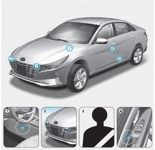
1. SRS control module/Rollover sensor
2. Front impact sensors
3. Side impact sensors (acceleration)
4. Side impact sensors (pressure)

Copyright © 2025 www.helantra7.com