
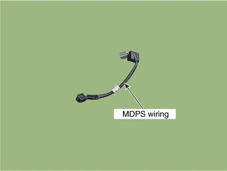
Hyundai Elantra (CN7): Motor Driven Power Steering / MDPS Wiring
Repair procedures
| Removal |
|

| 1. | Turn the ignition switch OFF and disconnect the battery negative (-) cable.
|

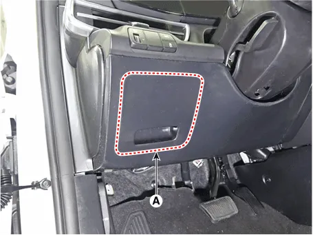
| 2. | Remove the fuse cover (A).
|
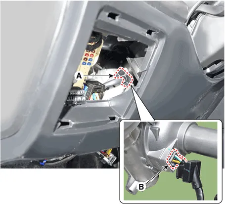
| 3. | Disconnect the grommet (A) and MDPS connector (B).
|

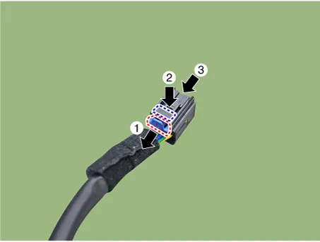
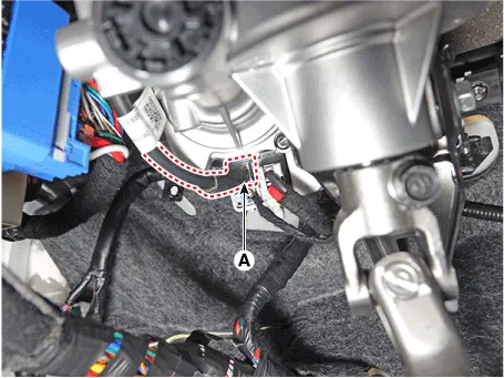
| 4. | Remove the wiring after disconnecting the MDPS connector (A).
|
| Installation |
| 1. | To install, reverse the removal procedures. |
Repair procedures Removal1.Loosen the wheel nuts slightly.Raise the vehicle, and make sure it is securely supported.2.Remove the front wheel and tire (A) from the front hub.
Other information:
Hyundai Elantra (CN7) 2021-2026 Service Manual: Heater Unit
Components and components location Component Location1. Heater unit assemblyCompoents1. Heater unit assembly2. Heater tube cover3. Heater core assembly4. Mode control actuator [LH]5. Dummy PTC6. Temperature control actuator [LH]7. Heater case [LH]8.
Hyundai Elantra (CN7) 2021-2026 Service Manual: Description and operation
D
Categories
- Manuals Home
- Hyundai Elantra Owners Manual
- Hyundai Elantra Service Manual
- Engine Control / Fuel System
- Driver assistance system
- Instrument Panel Overview
- New on site
- Most important about car

Copyright © 2026 www.helantra7.com - 0.0223