Hyundai Elantra: Engine Control System / Rail Pressure Sensor (RPS)
Hyundai Elantra (CN7) 2021-2025 Service Manual / Engine Control / Fuel System / Engine Control System / Rail Pressure Sensor (RPS)
Description and operation
| Description |
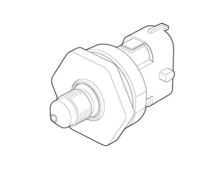
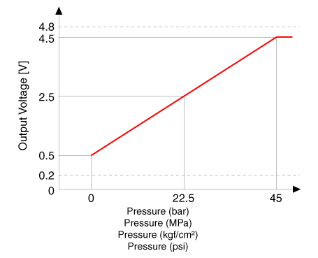
Installed on the delivery pipe, the Rail Pressure Sensor (RPS) measures the instantaneous fuel pressure in the delivery pipe. The sensing element (Semiconductor element) built in the sensor converts the pressure to voltage signal.
By using this signal, the ECM can control correct injection amount and timing and adjust the fuel pressure with the fuel pressure regulator valve if the target pressure is different from the actual pressure calculated by the RPS output signal.

Specifications
| Specification |

Schematic diagrams
| Circuit Diagram |

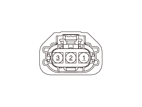
Harness Connector

Repair procedures
| Inspection |
| 1. | Connect the diagnostic tool on the Data Link Connector (DLC). |
| 2. | Measure the output voltage of the RPS at idle and various engine speed.
|
| Removal |
| 1. | Release the residual pressure in fuel line. (Refer to Fuel Delivery System - "Release Residual Pressure in Fuel Line") |
| 2. | Turn the ignition switch OFF and disconnect the battery negative (-) cable. |
| 3. | Remove the intake manifold. (Refer to Engine Mechanical System - "Intake and Exhaust System") |
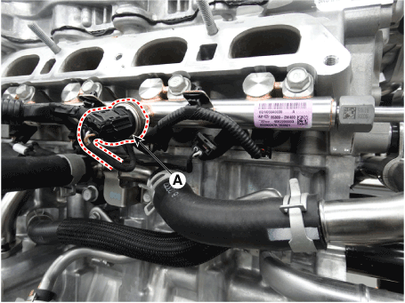
| 4. | Disconnect the rail pressure sensor connector and then remove the sensor (A) from the delivery pipe.
|
| Installation |
|
| 1. | Install in the reverse order of removal. |
 Oil Pressure Sensor (OPS)
Description and operation
DescriptionIt generates the oil pressure and temperature information (output voltage) to control the pump operation proportional control valve in variable oil pump system...
 Injector
Description and operation
DescriptionThe GDI injector is similar to a standard injector, but sprays fuel at a much higher pressure directly into the combustion chamber and has a swirl disc to get the fuel swirling as it exits the nozzle...
Other information:
Hyundai Elantra (CN7) 2021-2025 Service Manual: Wheel
Components and components location Components Steel wheel 15 inch (6.0J X 15) Aluminum wheel 15 inch (6.0J X 15) Aluminum wheel 16 inch (6.5J X 16) Aluminum wheel 17 inch (7...
Hyundai Elantra (CN7) 2021-2025 Service Manual: Dynamic Damper
Repair procedures Removal1.Remove the front drive shaft.(Refer to Driveshaft Assembly - "Front Driveshaft")2.Remove the trans axle side joint.(Refer to Driveshaft Assembly - "Transaxl Joint")3.Remove the dynamic damper band (A, B) using driver (-)...
Copyright © 2025 www.helantra7.com


.png)