Hyundai Elantra (CN7): Rear Suspension System / Rear Shock Absorber
Components and components location
| Components |
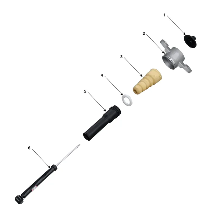
| 1. Insulator cap 2. Insulator 3. Bumper rubber | 4. Spacer 5. Dust cover 6. Rear shock absorber |
Repair procedures
| Removal |
| 1. | Loosen the wheel nuts slightly. Raise the vehicle, and make sure it is securely supported. |
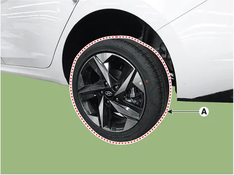
| 2. | Remove the rear wheel and tire (A) from the rear hub.
|

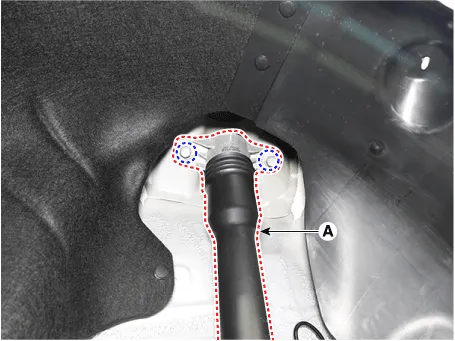
| 3. | Remove the rear shock absorber (A) from the body after loosening the mounting bolts.
|
| 4. | Remove the rear shock absorber (A) from the torsion beam axle after loosening the mounting bolt and nut.
|

| Disassembly |
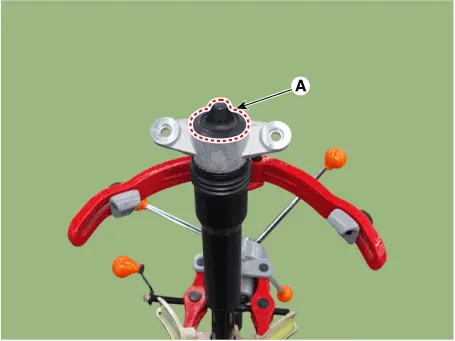
| 1. | Remove the insulator cap (A).
|
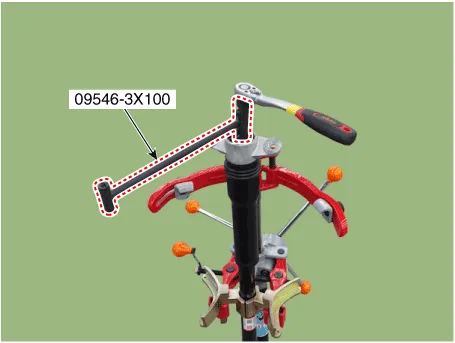
| 2. | Loosen the lock nut by using the SST (09456-3X100).
|
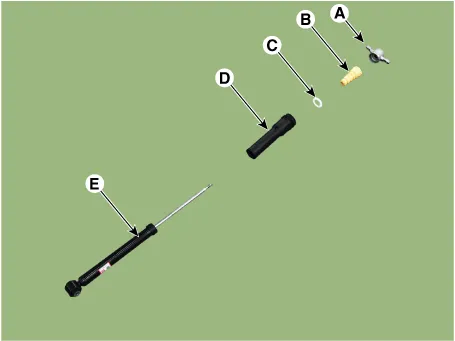
| 3. | Separate the insulator (A), bumper rubber (B), spacer (C), dust cover (D), shock absorber (E).
|
| Inspection |
| 1. | Check the rubber parts for wear and deterioration. |
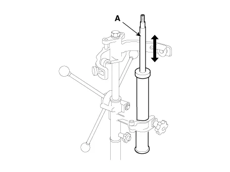
| 2. | Compress and extend the rear shock absorber rod (A) and check that there is no abnormal resistance or unusual sound during operation.
|
| 1. | Fully extend the shock absorber rod. |
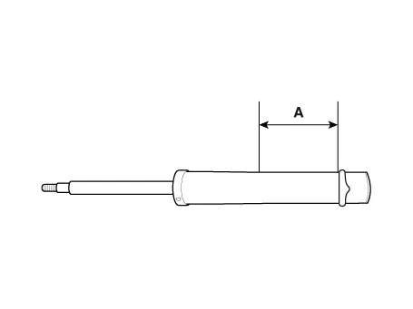
| 2. | Drill a hole to remove gas from the cylinder (A).
|

| Reassembly |
| 1. | To reassembly, reverse the disassembly procedure. |
| 2. | Using SST(09546-3X100), install the lock nut.
|
| 3. | Install the lock nut cover (A).
|
| Installation |
| 1. | To install, reverse the removal procedures. |
Components 1. Rear torsion beam axle2. Rear torsion beam chassis bracket3. Rear axle
Components and components location Components1. Coil spring upper pad2. Rear coil spring3. Coil spring lower pad Repair procedures Removal1.
Other information:
Hyundai Elantra (CN7) 2021-2026 Service Manual: Ignition Switch Assembly. Repair procedures
Repair procedures Replacement1.Disconnect the negative (-) battery terminal.2.Remove the crash pad lower panel.(Refer to Body - "Crash Pad")3.Remove the steering column upper & Lower shroud.4.Remove the ignition switch and disconnecting the Key Warning / immobilizer connector.
Hyundai Elantra (CN7) 2021-2026 Service Manual: Receiver-Drier
Repair procedures Replacement1.Remove the condenser.2.Remove the cap (A) on the bottom of the condenser with a L wrench. Tightening torque : 9.81 - 14.71 N.m (1.0 - 1.5 kgf.m, 7.2 - 10.8 lb-ft) 3.Remove the receiver-drier (A) from condenser using a long nose plier.
Categories
- Manuals Home
- Hyundai Elantra Owners Manual
- Hyundai Elantra Service Manual
- Rear Seats
- Integrated Thermal Management Module (ITM)
- Shift-lock release
- New on site
- Most important about car
