Hyundai Elantra (CN7): Fuses And Relays / Relay Box (Engine Compartment)
Repair procedures
| Inspection |
| 1. | Disconnect the negative (-) battery terminal. |
| 2. | Pull out the relay from the engine compartment relay block. |
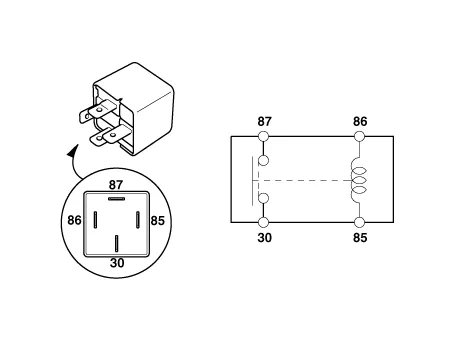
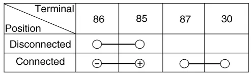
| 1. | After supplying power to between No. 85 and 86 power relay terminals, check that there is continuity between No. 30 and 87 terminals. |
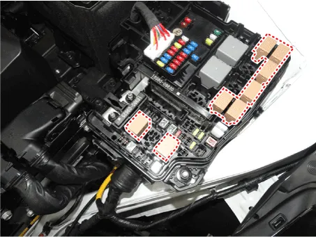
| 2. | After disconnecting power between No. 85 and 86 power relay terminals, check that there is no continuity between No. 30 and 87 terminals. Engine Room Relay Block
|
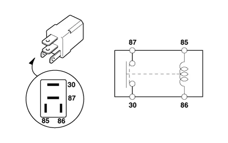
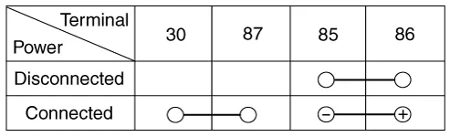
| 1. | After supplying power to between No. 85 and 86 power relay terminals, check that there is continuity between No. 30 and 87 terminals. |
| 2. | After disconnecting power between No. 85 and 86 power relay terminals, check that there is no continuity between No. 30 and 87 terminals.
|
| 1. | Disconnect the negative (-) battery terminal. |
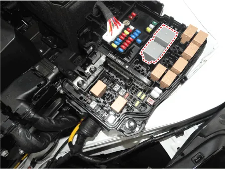
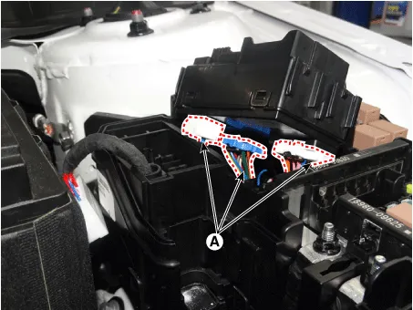
| 2. | Disconnect the PCB block connector (A).
|
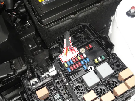
| 3. | Push the four hooks (B) in the direction of the arrow and lift up the PCB block (A).
|
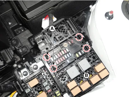
| 4. | Remove the PCB block by disconnet the connector.
|
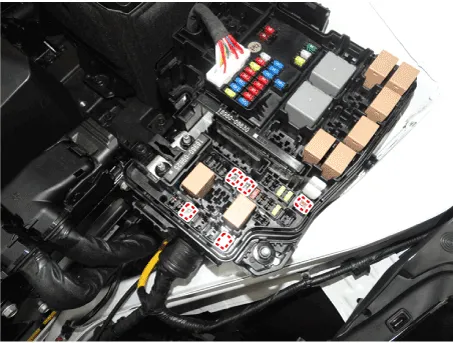
| 1. | Check that the fuse holders are loosely held and that the fuses are securely fixed by the holders. |
| 2. | Check that each fuse circuit has the exact fuse capacity. |
| 3. | Check the fuses for any damage.
|

|

Component Location[Engine Room]1. Engine room junction block[Interior Relay]1. ICU (Integrated Central Control Unit)
Repair procedures Fuse Inspection1.Check that the fuse holders are loosely held and that the fuses are securely fixed by the holders.2.Check that each fuse circuit has the exact fuse capacity.
Other information:
Hyundai Elantra (CN7) 2021-2025 Service Manual: Condenser
Components and components location Components Location[General type]1. Condenser[N Line]1. Condenser Repair procedures Inspection1.Check the condenser fins for clogging and damage. If clogged, clean them with water, and blow them with compressed air.
Hyundai Elantra (CN7) 2021-2025 Service Manual: Description and operation
DescriptionThe cruise control system is engaged by the cruise "ON/OFF" main switch located on right of steering wheel column. The system has the capability to cruise, coast, accelerate and resume speed.It also has a safety interrupt, engaged upon depressing brake or shifting select lever.
Categories
- Manuals Home
- Hyundai Elantra Owners Manual
- Hyundai Elantra Service Manual
- Drive Mode
- Engine Control / Fuel System
- Clutch System
- New on site
- Most important about car
